So, it is only because no 20v transformer at the market right?
I am planning to order a custom transformer for aleph J.
Actually, there are both 18V and 20V transformers available from Antek. Most people are using 18V with a diode bridge that only drops 1.2V. I have purchased an Antek 20V and plan on using it with the Aleph J build. I'm playing with liquid cooled, so I hope to have extra cooling available for the higher voltage.
Just curious, why the custom transformer?
That is cool project please post photos here 😉
Why custom?
Because I need an accurate power (especially for current)
Since, market transformers can not be trusted.
😛 so... I started my build, and i would like to show, how i made my pcb's real diy (just kidding).
-- deleted
I will post again, when i move on...
// Jesper

Didiet
I have the following voltages across R7/R8 are they close enough to spec
Left ch R7 5.27V R8 8.6V
Right ch R7 5.32 R8 8.6V
Picture to follow.
Left ch R7 5.27V R8 8.6V
Right ch R7 5.32 R8 8.6V
Picture to follow.
Nice work, that's exactly how I made my PCB's in the past... I remember having a special pencil with that dark blue color you have. What pencil do you use?
Can't remember the name...
Now I'm too lazy and just order the Diyaudio PCBs 😀
Walter
Can't remember the name...
Now I'm too lazy and just order the Diyaudio PCBs 😀
Walter
Pcb pensil
Hi WalterW.
Its a DALO pen / not very easy to find these days through.
I found them in a Danish shop...
DECON DALO #33 PC-BLUE #901, 1 stk. | Elektronik Lavpris ApS
// Jesper
Hi WalterW.
Its a DALO pen / not very easy to find these days through.
I found them in a Danish shop...
DECON DALO #33 PC-BLUE #901, 1 stk. | Elektronik Lavpris ApS
// Jesper
Aleph Kool J heatsink
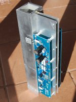
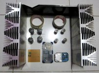
Still a long way to go, but I thought you guys might enjoy pictures of the liquid cooled heatsink. I've decided to call my little project, "Aleph Kool J" since the liquid cooling is the unusual part of this build.
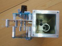
This is a cooling tower type of heatsink, my version of a concept that bcmbob did with his BA-3. The water flows in from the bottom and cools the outer square tube. An inner round tube is set at the height of output devices and allows water to return to the pump and radiator.
The first picture shows the heatsink in the mockup stage. I am playing with standoff height relative to output device mounting.
The second picture show the inside of the heatsink.
Still a long way to go, but I thought you guys might enjoy pictures of the liquid cooled heatsink. I've decided to call my little project, "Aleph Kool J" since the liquid cooling is the unusual part of this build.
This is a cooling tower type of heatsink, my version of a concept that bcmbob did with his BA-3. The water flows in from the bottom and cools the outer square tube. An inner round tube is set at the height of output devices and allows water to return to the pump and radiator.
The first picture shows the heatsink in the mockup stage. I am playing with standoff height relative to output device mounting.
The second picture show the inside of the heatsink.
Attachments
Great thing !!
I also brood long about watercooling the AJ.
But how about radiating the heat away from the square tube?
I also brood long about watercooling the AJ.
But how about radiating the heat away from the square tube?
Great thing !!
I also brood long about watercooling the AJ.
But how about radiating the heat away from the square tube?
I will use parts available for PC cooling. Basically, a pump to circulate the coolant, a radiator, and fan. Not cheap, but interesting.

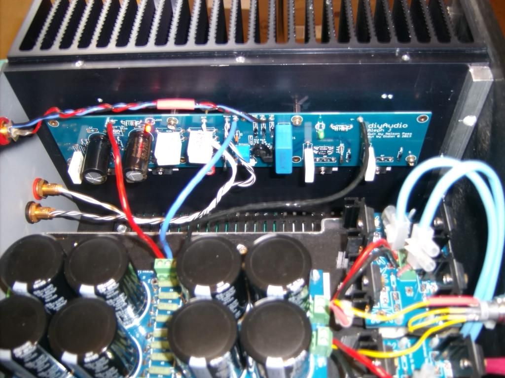
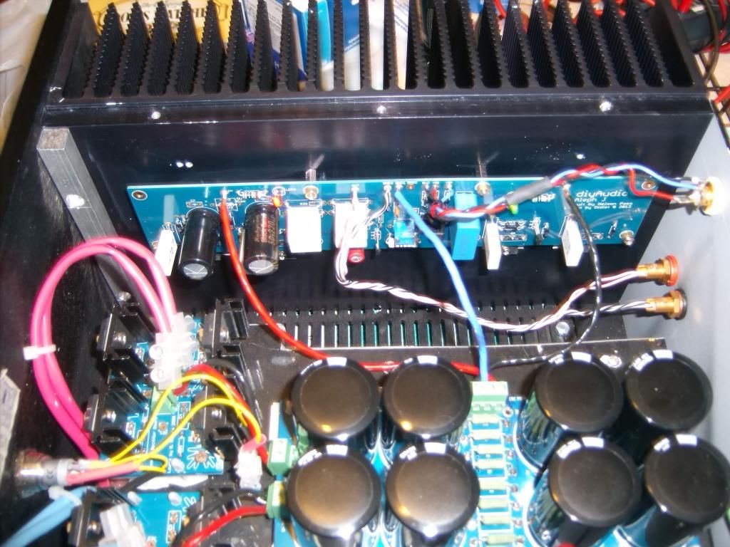
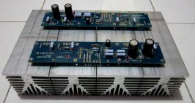
A few pics of my single supply build.Top;bottom & front panels are from Modushop with heatsinks from these guys in the UK
http://www.gdrectifiers.co.uk/uploads/010118.pdf


AndrewT will no doubt tell me to twist the wires.
http://www.gdrectifiers.co.uk/uploads/010118.pdf


AndrewT will no doubt tell me to twist the wires.
Last edited:
I can't tell, are the PS boards on a platform above a transformer? You have the inputs twisted and that's where it matters the most. As long as you have no hum then no more is needed. I like the front panel choice. Nice work!
Thanks guys.The transformer and a soft start board are on the amp base with as you say the rectifiers and power supply[cvillers excellent pcb's] on a platform above.The heatsinks sit at the mid 40's.I do have a slight hum but only noticeable with my ear against the speaker.Love the sound of this amp😀
I'm a slow builder, but enjoying the build process during weekend. My original plan was to use 6pcs heatsink per side and use 10mm copper plate to mount them. but after trying different layout, i can make each irfp fits into 1 heatsink. each heatsink profile is 200mmx84mm base dimension, with 7mm thickness of base plate and 81mm height with fins, weighted 1.6kg. hopefully it's enough.
I also try to prepare 2 UMS per side, prepare it one day for another FW
I also try to prepare 2 UMS per side, prepare it one day for another FW
Attachments
Here is the question: mouser did not send me 22K for IN - input. Can I run amp without it if I do not use balanced input and connect In- to the gnd?
Since I don't know my heatsink thermal conductivity, I find some similarity with the products on this website Heatsinks: 7000 series - 7200HS | Birmingham Aluminium Ltd and I made xls exercise for simulation as attached
Simulation result shows 0.47 °C/W per heatsink. let just say my heatsink profile is half less effective than birminghamalum products, κ will be 1 °C/W.
My question is, how much energy is dissipated from each irfp? Do they dissipate in equal?
Simulation result shows 0.47 °C/W per heatsink. let just say my heatsink profile is half less effective than birminghamalum products, κ will be 1 °C/W.
My question is, how much energy is dissipated from each irfp? Do they dissipate in equal?
Attachments
Last edited:
My heatsinks are the equivalent of these from Birmingham Al. and run at approx 45C if that helps.
Heatsinks: 1000 Series - 1633HS | Birmingham Aluminium Ltd
Heatsinks: 1000 Series - 1633HS | Birmingham Aluminium Ltd
- Home
- Amplifiers
- Pass Labs
- Aleph J illustrated build guide