Here is the latest creation (re-creation 😀) from the "badger hole"  .
.
- A really stable triple OPS - I've swapped outputs , hooked up without a zoble ...
all the abuse.
- This amp is 32 years old and I'm still abusing it daily (just needed a re-cap).
-My LT simulation worked first time , needed to tweak the unconventional compensation scheme - it never exhibited any instability even without the "tweak" .
- Since I actually own the real live amp (and listen to it a lot) , I was able to
compare LT's output to the real world operating points - 99% accurate.
Below are the "goods"
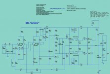
The schematic and the .ASC (spice file)
PS - the PCB is next , I REALLY like this little amp. (try to guess who designed it ? )
OS
.- A really stable triple OPS - I've swapped outputs , hooked up without a zoble ...
all the abuse.
- This amp is 32 years old and I'm still abusing it daily (just needed a re-cap).
-My LT simulation worked first time , needed to tweak the unconventional compensation scheme - it never exhibited any instability even without the "tweak" .
- Since I actually own the real live amp (and listen to it a lot) , I was able to
compare LT's output to the real world operating points - 99% accurate.
Below are the "goods"
The schematic and the .ASC (spice file)
PS - the PCB is next , I REALLY like this little amp. (try to guess who designed it ? )
OS
Attachments
Member
Joined 2009
Paid Member
I see you are back in the saddle on this one 😀
Looks like a good solid performer from the schematic. All those LTP's - could include a balanced input option ?
Looks like a good solid performer from the schematic. All those LTP's - could include a balanced input option ?
Could the board occupy just 1/3 of the UMS so we can make a 4-6 channel GLA in a store 4u case? That would improve my system's SAF.
I see you are back in the saddle on this one 😀
Looks like a good solid performer from the schematic. All those LTP's - could include a balanced input option ?
I'm not , but sansui sure was in 81' .
Here's some specs :
- .02% THD20 on the simulator, .03% rated in the OEM manual.
.002% full power @ 1K
- -107db noise. My real amp is noiseless (ear to tweeter-full volume).
I'm surprised they put such a good amp in a "mid-fi".
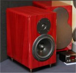
With my digital source(SB live -PC) , this really sounds wonderful on the Dan Richie audiophile 2-ways in the workshop.
(below link and attachment) X-LS Classic kit
The circuit - I've found that by loading the VAS (R25 -47K) you can control
the H2 / H3 balance in the Fourier results. 22k gives H2 dominant at the
expense of total THD. 33K seems to be the sweet spot , at least for these models.
The real amp uses 2sa992 /2sc1845 almost exclusively , 50VDC rails.
The longevity of this circuit is amazing .... found it in the college of Saint Rose dumpster
( many beer- soaked "enhancements" of "higher education"
).It worked at lower volumes even with dry electrolytics -amazing.
The compensation is "weird" . I know C17 (lead comp.) and it's effect/purpose.
I'm curious about R7 /C5. I don't know what this network is called , but it greatly contributes to this amps stability.
The amp also exhibits the best clipping behavior , I would guess most of
32 years of clipping 😀 .
OS
Attachments
Could the board occupy just 1/3 of the UMS so we can make a 4-6 channel GLA in a store 4u case? That would improve my system's SAF.
I would just go for a couple RSA's. (really sarcastic acronyms)
At least I gave a circuit , unlike the "revolution class a/b thread" ... with
78 replies and over 3000 views.
Too many EF2 OPS's around here.
If I scale this up to a mje340/350 - njw0302/0281 - mjl21193/94 output stage,
perhaps builders will be a little less apprehensive of triples.
OS
Member
Joined 2009
Paid Member
The Pioneer amplifier I moded into my TGM6 amplifier (there's a thread with schematics somewhere around here) which also has this 'R25', same value in fact. The load on the VAS was a key part of the compensation (like your R7 C5) as it also had no Cdom. The lead comp does seem a little large at 22pF, but not by much.
I love the speakers - red, great colour. I hope these weren't punished with 32 years of clipping !
I love the speakers - red, great colour. I hope these weren't punished with 32 years of clipping !
Ahhhh .... while others are asleep and fussing over the "revolution" , I
continue to dissect this cool circuit.
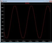
Attachment 1 shows the clipping behavior. At least it is symmetrical , but
shows a small amount of "sticking" . The edges are rounded , not as bad as
"blameless" clipping.
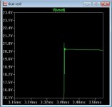
Attachment 2 is driving a capacitive load. I had to really coax this amp to
give me a damped ringing response. Bridged the OP inductor , lowered the
load resistor. VERY stable ... I've not simulated too many like this.
All this is reflected in the real amp , 32 years with original semi's is a pretty good track record .....
This must become a project !
OS
continue to dissect this cool circuit.
Attachment 1 shows the clipping behavior. At least it is symmetrical , but
shows a small amount of "sticking" . The edges are rounded , not as bad as
"blameless" clipping.
Attachment 2 is driving a capacitive load. I had to really coax this amp to
give me a damped ringing response. Bridged the OP inductor , lowered the
load resistor. VERY stable ... I've not simulated too many like this.
All this is reflected in the real amp , 32 years with original semi's is a pretty good track record .....
This must become a project !
OS
Attachments
The Pioneer amplifier I moded into my TGM6 amplifier (there's a thread with schematics somewhere around here) which also has this 'R25', same value in fact. The load on the VAS was a key part of the compensation (like your R7 C5) as it also had no Cdom. The lead comp does seem a little large at 22pF, but not by much.
I love the speakers - red, great colour. I hope these weren't punished with 32 years of clipping !
That was the "stock photo" of the AV123's , I have piano gloss black ones "made in Cali,Columbia"
(checked the boxes for contraband 😀- found these
outside a local tavern - perfect condition).
I'm nice to my AV123's - I use them as a reference to hear the imaging and
subtleties of my amps , for clipping I use my "bombed out" realistic 3-ways
(10"/5"/3") - only $20 , even with new woofers.
I haven't done much amp stuff lately , I have been increasing my loudspeaker
"collection".
OS
Too many EF2 OPS's around here.
If I scale this up to a mje340/350 - njw0302/0281 - mjl21193/94 output stage,
perhaps builders will be a little less apprehensive of triples.
OS
Way too many. Especially when they parallel a dozen or so outputs and think they can drive an ohm. And then wonder why the VAS runs out of gas at normal current levels. I hate to run VAS's at 50mA because they burn up the PCB and drift all over the place. Much better to use EF3 with a couple miserable mA in the predriver.
A lot of builders have trouble with triples (tribbles?) because they insist on doing weird things with them. A straight complementary EF3 is pretty darn stable with either high or low fT parts in the driver/predriver.
I came to these same conclusions after reviewing some of the more popular
threads that use those EF2's with 5 or more OP's and claim 2R loads.
In the attempt to not "run out of gas 😉" VAS wise , some are using drivers
to do the job. Besides the much higher Cob of these devices (mje15032/33 or
2sa1837/2sc4793 -not too bad) , you also have a limited choice of a 1A SOA drivers to run 5 or more pairs of "hungry" outputs.
Moon audio and other overpriced 😀 high-end amps use outputs as drivers. You can't (or shouldn't)
do this with the standard EF2.
I have the opinion that 3 pair of outputs is the maximum for the EF2.
OS
Very nice and refreshing amplifier considering the "current"
subjectivists tendencies , it should allow very good perfs
that might well surprise some esoterics design afficionados...
No doubt that i ll give it a try in the simulator...🙂
Stability would be greatly improved with say a 22pf from
collector to base of Q7.
Also , what happened to Q7/Q11.?.?..😉
subjectivists tendencies , it should allow very good perfs
that might well surprise some esoterics design afficionados...
No doubt that i ll give it a try in the simulator...🙂
Stability would be greatly improved with say a 22pf from
collector to base of Q7.
Also , what happened to Q7/Q11.?.?..😉
That 22pf would add what would normally be a 'cdom' - in this case, extra phase shift. Since the amp is already lag compensated (R7 C5) this may or may not help stability. If you remove the lag comp, you need it or else. And maybe a higher value would be advisable.
Sansui 3900/5900
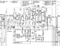
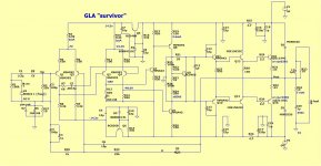
Here is the "truth" 🙂.
Attachment 1 is the amp section. The input stages (I tested them) are run by
a +/- 18VDC supply. It is strange they regulate the positive 18v from the amps main
V+ rail and derive just the negative 18V for Q1-2 from an auxiliary supply.
I might "clean up" the differential supplies and create two zener regulated
ones instead , it will make for a "standalone amp".
This is really a Sansui Z3900 , the PDF is too big.
You will notice the Sansui had a DC servo - I changed this into it's passive
equivalent.
OS
Very nice and refreshing amplifier considering the "current"
subjectivists tendencies , it should allow very good perfs
that might well surprise some esoterics design afficionados...
No doubt that i ll give it a try in the simulator...🙂
Stability would be greatly improved with say a 22pf from
collector to base of Q7.
Also , what happened to Q7/Q11.?.?..😉
Here is the "truth" 🙂.
Attachment 1 is the amp section. The input stages (I tested them) are run by
a +/- 18VDC supply. It is strange they regulate the positive 18v from the amps main
V+ rail and derive just the negative 18V for Q1-2 from an auxiliary supply.
I might "clean up" the differential supplies and create two zener regulated
ones instead , it will make for a "standalone amp".
This is really a Sansui Z3900 , the PDF is too big.
You will notice the Sansui had a DC servo - I changed this into it's passive
equivalent.
OS
Attachments
Last edited:
Zener supplies
Very good !
Lower distortion 🙂 .... .008% THD20K 8R
Used 15V zeners with 2 simple follower trannies (below).
One pair of differentials (Q1-2) sees 12v and the other (Q3-4) 35V.
Many choices here !
Sansui made some economic choices and just "stole" existing supplies
for the differential to save $$$$ .
Much more stable , I can change the Q1-2 Ic over a much wider range without
oscillation now ,as well.
PS - scaled down R8-9 to 3K3 to keep things "vintage".... (-14.4VDC instead of -18VDC)
OS
Attachments
Last edited:
OMG -Q7 and 11
😱 😱
But it actually simulated right - 😕
I fixed this - and wow ! .001% 20k.
- Tiny glitch in the stages is gone , and the loop gain is "more normal"
(typical) 500k UG with 80+ margin....
-Q1-2 nearly superimpose (balanced)
-Q1-2 are 1ma , Q2-3 are 2ma , the VAS is 3ma.
The actual amp measures real close to this.
This is almost ready to FLY! (pcb)
PS- this amp's topology was actually able to compensate for 2 swapped E-C's !
New .ASC (below)
OS
Attachments
Last edited:
Hi, OS!
Very nice amp, indeed.
Probably I did not get it right, but it isn't a little too much 50 V rails for a single pair? I see that you have used good robust ONSemi outputs, but you can be sure that sooner or later somebody will hook some 4 Ohm speakers on it.
I would be tempted to put 3 pairs on output and call it a good 250 Watter!
Hi, OS!
Very nice amp, indeed.
Probably I did not get it right, but it isn't a little too much 50 V rails for a single pair? I see that you have used good robust ONSemi outputs, but you can be sure that sooner or later somebody will hook some 4 Ohm speakers on it.
I would be tempted to put 3 pairs on output and call it a good 250 Watter!
I'll design a single pair MJL21193/94 version first. Using the triple OP stage
demands it. That should give about 80W/channel (8R) ,the MJL's soa would also be good enough for a 4R load at 40V rails.
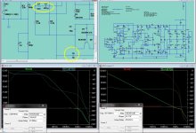
Solved the compensation issue. Standard miller comp. with a B-C capacitor
won't work with this amp !
Phase compensation -(R7/C5) of the first differential plus a little lead compensation from the VAS (R6) let's you "shape" the phase margin and unity gain point of the amplifier response curve. Harder ! , but a more elegant
approach. Original "vintage" (47R and .0022uf) values still gave a stable amp.
(below attachment)... this amp is compared to the standard "blameless".
Latest .ASC below - (with the "vintage" parts modeled) the performance came out real close to the OEM specs - but just a little better.
OS
Attachments
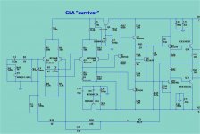
GLAv1.2 (final)
All is wonderful ... 🙂
V1.2 is SO close to the Sansui 3900 , both in compensation and actual voltages.
(Attachment 1) is the final work.
My tweaks to C6 (lead comp.) and the "lag" comp. (R7/C5) are within range
of the original specs.
The simulation also allows for higher Hfe Zetex devices , 2n5401's , 2sa992's
or any other to-92 device for Q1-4.
Any to-220 (mje15032/33 , 2sa1837/2sc4793) as driver , and any OP device
..including the low gain/low Ft mjl21193/4... work very well with this amp.
R25 and 26 load the VAS , which gives a monotonically decaying harmonic
output.
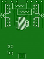
The differentials and VAS are at such low current (no heatsinks),
I can squeeze this into a 76 X 102 mm board for the 70W version (attachment 2).
The main board will use njw TO-3P's as drivers !!
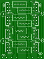
For those who want the "Frankenstein" version , attach the "GLAeX" PCB
(attachment 3).Run your 80V rails, you will have a 400W true triple OPS.
Also , the final .ASC is also below.
PCB's + the BOM will be done in the next few days.
OS
All is wonderful ... 🙂
V1.2 is SO close to the Sansui 3900 , both in compensation and actual voltages.
(Attachment 1) is the final work.
My tweaks to C6 (lead comp.) and the "lag" comp. (R7/C5) are within range
of the original specs.
The simulation also allows for higher Hfe Zetex devices , 2n5401's , 2sa992's
or any other to-92 device for Q1-4.
Any to-220 (mje15032/33 , 2sa1837/2sc4793) as driver , and any OP device
..including the low gain/low Ft mjl21193/4... work very well with this amp.
R25 and 26 load the VAS , which gives a monotonically decaying harmonic
output.
The differentials and VAS are at such low current (no heatsinks),
I can squeeze this into a 76 X 102 mm board for the 70W version (attachment 2).
The main board will use njw TO-3P's as drivers !!
For those who want the "Frankenstein" version , attach the "GLAeX" PCB
(attachment 3).Run your 80V rails, you will have a 400W true triple OPS.
Also , the final .ASC is also below.
PCB's + the BOM will be done in the next few days.
OS
Attachments
Wow, very nice map OS! The "Frankenstein" version is going to be my next project. 🙂
By the way, the name 'Survivor" reminds me of the 80s band that did the theme song "Eye of the Tiger" for Rocky III, a fitting name for a simple, rugged & quality amp. 😛
By the way, the name 'Survivor" reminds me of the 80s band that did the theme song "Eye of the Tiger" for Rocky III, a fitting name for a simple, rugged & quality amp. 😛
Last edited:
- Home
- Amplifiers
- Solid State
- GLA (good little amp) "survivor"