It is a very low bar, Andrew...You're trying to confuse Members.
I get called Andrew T.
That is different from Bonsai.
But some members insist on revealing other names, your's for instance, seems to be Andrew.

Don't try to set the bias with the bulb tester in line.
When you remove the bulb tester the bias usually changes and usually it rises when the supply voltage increases.
I always recommend that the bulb tester be removed for bias setting.
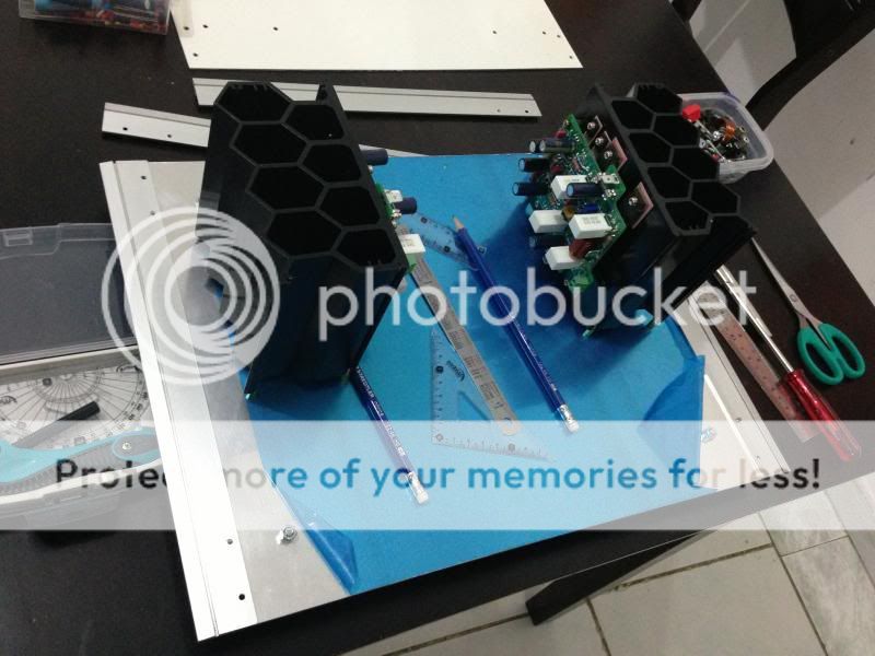
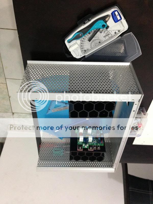
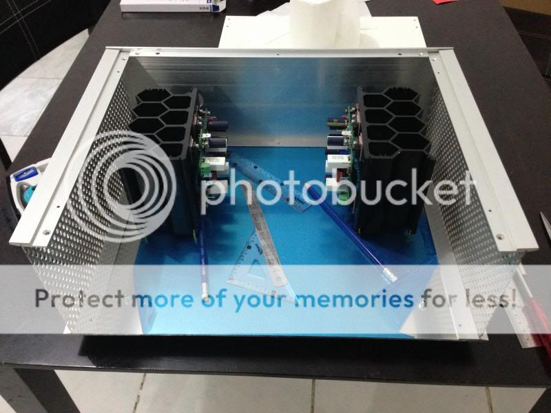
Thanks Andrew T but I will do the final adjustment without a LIGHTBULB once I made a chassis, right now i'm busy building one 🙂.


Regards,
Junie
Andrew T,
Yes, my name is Andrew.
PMI - it's a good name 😀
Junie, that amp of yours is looking very, very nice. Looking forward to seeing the final build!
Yes, my name is Andrew.
PMI - it's a good name 😀
Junie, that amp of yours is looking very, very nice. Looking forward to seeing the final build!
Yes, and popular... 😀PMI - it's a good name 😀
Confusion with names online IS a low bar to set however, especially when names on Diyaudio do not match Paypal names, or mailing addresses... the clairvoyance bit of DNA is sadly absent in my family genealogy 🙄
But every name on DIYaudio is unique. Deliberately so !!!!!!Yes, and popular... 😀
Confusion with names online IS a low bar to set however, especially when names on Diyaudio do not match Paypal names, or mailing addresses... the clairvoyance bit of DNA is sadly absent in my family genealogy 🙄
Hi Junie
This is good full DIY

I still continue my listening of my NX amp and I am still impressed how good it sounds

Once I have the chance to do listenings with my DIY friends I will post their impressions....
So for the other members hurry up completing your NX to enjoy 🙂

Fab
NX write up mentions R32 and R33 collector load resisitors for TIS transistors. There are no R32 and R33 on the schematic, only R30 and R31, and R22 and R23.
25. NX write up mentions R32 and R33 collector load resisitors for TIS transistors. There are no R32 and R33 on the schematic, only R30 and R31, and R22 and R23.Latest doc update list.
If there are any further comments about the PCB, let me know and I'll include them in the update.
1. Correct circuit –Q9 and Q11 – cannot use BC547 and BC557 devices – their max Vceo is 45V. Use BC546 and BC556 because their Vceo is 65V; OK to use ‘B’ devices
2. Also ok to use lower gain grade devices for TIS transistors KSC3503 and KSA1381 but must be the same gain grade
3. Comment on TIS current – sim’d and measured difference and why this is so - check TIS current – doc says 25mA, sims say 28mA measured is 43mA
5. Talk about option to increase TIS emitter resistors to say 22 or 27 Ohms
6. Check front end buffer load resistors – 4.7k or 10k? has big impact on TIS current
7. Add coil winding details: 8 turns of 2mm thick solid copper wire on 10mm former. Total outside diameter of coil is 14.25mm and total length is 17mm. Add photo as well.
8. Add transistor pin-out diagram page.
9. Correct supply voltage shown on circuit diagram – says +-20V - must say +-50 V maximum
10. Slew rate and small signal rise time numbers - you did not differentiate these two terms clearly in the doc.
11. Discuss Loop compensation - Add a section to cover this with original LTspice plots
12. Clean up main filter capacitor spec in document: 22mfd 50V (remove reference to 47mfd device)
13. Correct circuit diagram of protection circuit – R15 and R16 are 100k (shown as 22k on circuit. Note PCB is correct)
14. Tighten up description of transformer secondary voltage vs load spec. 34-0-34 at 5% regulation will give 49V
15. Check and correct BOM lists following on from above points.
16. Add points and plots to show that the nx-amp input stage does NOT go into class B
17. Change the output transistor holes to 1.6mm on the PCB’s
18. Move the 2.7k logos on the feedback resistors – they are need to be centralized within the resistor ouline
19. Check PSU main capacitor holes – make them a bit bigger
20. Cover capacitive coupling the input and how to do it.
21. Update PCB to remove 100k resistor on input - not needed
22. Check BOM list
23. Propose alternative transistors for the drivers
24. Add procedure to check VAS current.
Updated list
Hi Bonsaï
Some items to possibly discuss in your article:
1)Why there is no need for small film bypass cap close to output BJT?
2)Could we increase the RC value on supplies to isolate/filter more the front end from output stage? For example 330uf/63v and 33 ohms instead of 220uf and 15 ohms.
3) reduced close loop gain and effect on stability or compensation cap value.
Thanks
Fab
Hi Bonsaï
Some items to possibly discuss in your article:
1)Why there is no need for small film bypass cap close to output BJT?
2)Could we increase the RC value on supplies to isolate/filter more the front end from output stage? For example 330uf/63v and 33 ohms instead of 220uf and 15 ohms.
3) reduced close loop gain and effect on stability or compensation cap value.
Thanks
Fab
Sure
Yes - the bias current is very stable, provided your heatsinks are adequate. also, very easy to put some heatsink compoun between the power device and the BC847 if needed, but I never did.
Sure
Can you also add:
1) R32/R33?value related to PSU DC voltage supply, I use +/- 42vdc thus I get about 25 ma on TIS with 1k ohms value.
2) bias current is difficult to adjust with potentiometer. Maybe use higher series resistor and lower pot value to desensibilize and ease adjustment of bias.
3) dcoffest adjustment with or without input shorted.
Thanks
Fab
Fab, the current in R32 and R33 is set by the front end Zener voltage and R28, R29 and R34 to R36. I will explain this in the document more clearly. R32 and R33 are not related to the supply voltage - they must be 1k.
- Home
- Amplifiers
- Solid State
- SX-Amp and NX-Amp
