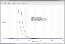
Thanks and interesting, Andrej said we can leave the 10uF MKT out if one likes that sound as best. But that is with the 2,2mF alone, what happens if one goes huge with a example 35F alone, what happens up higher where such huge cap has less bite because of induktor effect.Well, i thought about this and made some sims. (Can interest L.C. as well).
Considering the few DC mV on this cap, it would be interesting to try a super/ultra capacitor (double layer) here and listen if any difference?
My eyes is on Cooper Bussmann HV 35F ESR 0,022 at 1Khz. My concern is that it is not tested in the VSSA setup, and do i have skills and equipment for measuring in live setup ?...
I have bought 6,8mF FR ø12,5 that i will test at some time alone without the 10uF MKT.
I attach nice images of simulation for groupdelays with vertical 500uS and 1uS, when looking on 1uS vertical it would be nice to have 35F to be stable in circuit for high end folks and studio setups.
Attachments
BRITT, you have to figure-out the sensibility of human ears to group delay vs frequency is max 1ms at 3Khz. (we are more sensible to the differences to localize) While, down to 500Hz, it is > 3.5ms increasing of 0.5ms by octave while the frequency decrease if i remember well.
(we are more sensible to the differences to localize)
I doubt any phase correlated difference can be noticed with anything greater than the original 2200µF here.
On the contrary, i wonder how long your monstrous 35F cap will take to be fully charged with a 2.5mA current source ?
My 100 000µF value was chosen to get a flat distortion curve. And i believe anything more is both useless and will only bring negative effects.
Last edited:
Christophe you are probably right and know much more about electrically goods and bads, and maybe it is impossible to real world. I admit i haven't heard VSSA yet, but working on the building process.My 100 000µF value was chosen to get a flat distortion curve. And i believe anything more is both useless and will only bring negative effects.
But i know my current setup is pure DC means coupled and sounds great, and have some country recordings "Elvis Presley and Willie Nelson" which have very low rumple errors which sounds real and great in that setup. This is why i care for the lows timing because every time i put caps in my present setup even with a corner frequency like your 100mF the realness in those recordings gets lost, and that is why i "dream" do overkill with the caps.
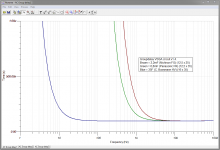
But think you must admit it is a nice plot with those 35F caps, i attach new plots with added 100mF. And one plus with 100mF or 35F is that the DC biasing level at position would be stable even long after amp turnoff 🙂.
Ricky
Attachments
Last edited:
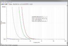
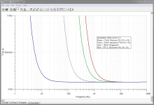
My concern was this (see attachment), where red is 2200µF and green 100 000µF.
Looking at your plot, and at 30Hz, we can see 100 000µF give a real 'no delay'.
To compare with the best enclosure i know, in this domain: http://www.moonaudio.fr/Photos taille affichage/group delay.jpg
May-i suggest you use a 5ms scale, and consider anything lower than 1ms as not a concern.
It is just like looking at harmonic distortion numbers lower than 0.005%.
There is many things more important, omho, like resonances, inductances and ESR of the caps at this critical position.
More interesting is the way those caps will "sound" in real, and that can be decided only after careful listening sessions, as L.C. do.
Attachments
I would like to change global feedback of my VSSA breadboard to make the amplifier into a current source. Is it as simple as placing a resistor between the output and the speaker and moving the feedback point to that junction? Sort of a Howland Current Pump modification?
Attachments

Last edited:

I'm curious. What for ?I would like to change global feedback of my VSSA breadboard to make the amplifier into a current source.
Can be, but very tricky, depending of the load: Need some luck with the load and careful adjustment of feedback serial resistances.padamiecki said:...but I am not sure if vssa will be stable after this mode.
Simulated bass loudspeaker as model, see attachment.
Attachments
Last edited:
I got very strange result on pure 6 Ohms (+1) resistance load and sin in input:
[edit]Trying a little further, the response is no, you can't.
Need too much mods, as you can 't reduce enough the serial feedback resistances: It has a direct influence in currents of the amp's input stage. Such a project would be possible, but need deep modifications. Better try an LTP (VFA) Amp for this kind of project.
Hacking the VSSA for such an usage may looks like breaking a diamond Jewell to make a PU needle ;-)
Attachments
Last edited:
I'm curious. What for ?
Can be, but very tricky, depending of the load: Need some luck with the load and careful adjustment of feedback serial resistances.
Simulated bass loudspeaker as model, see attachment.
Pure current source prevents back emf from distorting the current at high speaker excursion.
I got very strange result on pure 6 Ohms (+1) resistance load and sin in input:
[edit]Trying a little further, the response is no, you can't.
Need too much mods, as you can 't reduce enough the serial feedback resistances: It has a direct influence in currents of the amp's input stage. Such a project would be possible, but need deep modifications. Better try an LTP (VFA) Amp for this kind of project.
Hacking the VSSA for such an usage may looks like breaking a diamond Jewell to make a PU needle ;-)
Vout is not as important as the voltage across the shunt resistor. Use the RLC load and plot the voltage across the shunt resistor for a sine input. The speaker is a resistor only at Fs. For all other frequencies, the speaker is an RLC.
Also, please try the shunt/sense resistor at the high side like a Howland current pump.
Would increasing serial feedback resistance be the proper direction?
Last edited:
You mean with a positive feedback ?Also, please try the shunt/sense resistor at the high side like a Howland current pump.
As i said, the VSSA is the worse topology to play with this kind of amusements for a simple reason: the network feedback impedance has a direct influence both on the bandwidth and the input stage currents.
Last edited:
More about fighting against Eddy currents effects in moving coils ?Pure current source prevents back emf from distorting the current at high speaker excursion.
I had played a lot with this, as well as servo-ing the speaker's membrane excursions (double moving coil or other kind of captors). Gave it up.
But i always use complete impedance compensation (Motional and inductive) of my speakers in order to get a flat impedance curve with all of them before any filter's work.
Last edited:
More about fighting against Eddy currents effects in moving coils ?
I had played a lot with this, as well as servo-ing the speaker's membrane excursions (double moving coil or other kind of captors). Give it up.
This is a scope shot of the voltage across a speaker (yellow) and the voltage across a 0.1 ohm shunt (blue) at high excursion. The current is undistorted until it reaches 2.8A pk. After that, the peak never increases; only a folded version of itself appears beside the original peak. I believe this is back emf and not eddy currents.
What software do you use for your simulation? Is it freeware? Can you share your .asc file and allow me to try some variations on your setup?
BTW, for woofer testing, this plot is BEAUTIFUL.
Attachments
1- LTSpice1-What software do you use for your simulation?
2-Is it freeware?
3-Can you share your .asc file and allow me to try some variations on your setup?
2- Yes.
3- http://www.esperado.fr/temp/VSSA/cfa-vs-vfa.html
Several remarks.
EMF is correctly addressed, omho, with what i call "motional impedance compensation".
I really believe the only interest for current source for speakers is to reduce distortion due to Eddie currents. Low source impedance of voltage amps is a very good way to damp speakers resonances, that you loose with high impedance current sources.
A CFA is yet "expansive", current source amplifier makes a "compressive" vfa, in a way, expansive too. Better to use VFA for this kind of purpose. And a LTP high impedance negative input let-you free for all changes in the feedback return network with no other negative consequences.
VSSA looks simple, but it is very tweaked and carefully tuned by L.C. Any change in impedances or current will have a direct and huge impact on distortion too.
I strongly suggest to not modify anything in this pure jewel, apart the input low filter capacitance if you know what you are doing.
Last edited:
1- LTSpice
2- Yes.
3- http://www.esperado.fr/temp/VSSA/cfa-vs-vfa.html
Several remarks.
EMF is correctly addressed, omho, with what i call "motional impedance compensation".
I really believe the only interest for current source for speakers is to reduce distortion due to Eddie currents. Low source impedance of voltage amps is a very good way to damp speakers resonances, that you loose with high impedance current sources.
A CFA is yet "expansive", current source amplifier makes a "compressive" vfa, in a way, expansive too. Better to use VFA for this kind of purpose. And a LTP high impedance negative input let-you free for all changes in the feedback return network with no other negative consequences.
VSSA looks simple, but it is very tweaked and carefully tuned by L.C. Any change in impedances or current will have a direct and huge impact on distortion too.
I strongly suggest to not modify anything in this pure jewel, apart the input low filter capacitance if you know what you are doing.
Thank you very much. I will investigate your observations.
Hi Esperado/woofertester i followed the last posts, and thinks about the target you are trying to reach must be to amend the bads of a speaker load.
Is this also reachable by doing a "complicated network circuit taylored to the specific speaker" to replace the 2,2mF feedback cap position in the original circuit schematic. Because circuit then be taylored to a specific speaker, a consequence be the amp not to be used with other speakers without the network be amended.
Is this doable in real World ?.
Ricky
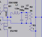
I see more this cap as a way to increase the input stage AC gain (fixed then by the emitter and collector resistances), than set in purpose to act on the feedback network itself. Since, it has a positive effect to decrease the impedance on the emitter, hence increase bandwidth....the 2,2mF feedback cap position
In DC, the current in input stage and VAS is fixed by the current source, and gain reduced to 1, helping to fix the amp DC offset.
The problem with any mod of the feedback resistances are that a part of the current provided by the current sources flows across the feedback resistances, and any change in the seriel feedback resistances will modify this amount, hence the part feeding the input active devices themselves, with, as consequence, the VAS current as well. The feedback impedance is an important part of the phase behavior of the closed loop too...
So, each time you try an other feedback impedance, you'll have to modify the current source to keep the quiescent current unchanged in the input devices, and, probably, work on the miller cap value too.
Not comfortable at all.
You can play during hours with this in simulators, looking each times at harmonic distortion values, the only conclusion you will reach is L.C. knows damn well what he is doing 🙂
Last edited:
Yes the VSSA is perfect amp to exchange the old amp and get better sound.L.C. knows damn well what he is doing 🙂
But in special setups to amend speaker behave, ideas is nice to have a look at.
Christophe comment this: Take your speaker model network i attach as picture and put it in VSSA circuit, now if circuit needs changes do not change feedback network but do complicated networks at the two 2,2mF caps positions instead to amend the hole circuit to behave god. Those two new networks will probably get complicated ala your speaker model Network.
Ricky
Attachments
Christophe,
I was following a thread you had about the conjugate network for correcting the impedance curve of a loudspeaker. Is that thread still going? I was very interested in that thread but stopped getting any updates. That would be directly related to what woofertester was asking about.
I was following a thread you had about the conjugate network for correcting the impedance curve of a loudspeaker. Is that thread still going? I was very interested in that thread but stopped getting any updates. That would be directly related to what woofertester was asking about.
Just to clarify, I am not looking to correct speaker impedance. I am looking to remove current distortion at large speaker excursions. I posted a scope shot of the current in a real 12"speaker moving 75 to 100 mm p-p. The back emf fights the forward emf. I want to produce full power output with a perfect current signal. I desire this condition so that I can measure properties of the speaker with a constant current. How it sounds is not relevant. However, I postulate that if loudspeaker distortion is lower operating this way, then it may sound better than driven with a voltage controlled amplifier. I also think that motional feedback will be better implemented if the inner loop is a current controlled amplifier.
My thinking with the VSSA is that if the front end uses current feedback then the overall feedback loop could be operated in current mode. It may be just wishful thinking but I have a breadboarded VSSA to tinker with and we shall see how that works.
My thinking with the VSSA is that if the front end uses current feedback then the overall feedback loop could be operated in current mode. It may be just wishful thinking but I have a breadboarded VSSA to tinker with and we shall see how that works.
- Home
- Vendor's Bazaar
- VSSA Lateral MosFet Amplifier