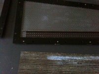
well got one together. eficiency is low , verry low around 80-82 dB. spacer distance is 1.5 mm. it goes as low as 56 hz where there resonance of the panel is and then rapidly drops off. i did measure some stuff, but my holmimpulse crashed when i wanted to save JPG..... so ill do it tomorow again. i know you cant close mic them because of proximity and no cancelation but it does looks funny, such a straight line 🙂
but one question remains, does anyone have a clue to calculate the efficiency when i triple the panels surface ? i had a 1.2 Ohm resistor in series with a 2 ohm load of the thing itself.
3.2 is still something my amplifier is pretty happy with. to make calculations easy.
because i would like to build a grown up version, but eficiency really has to increase. 80 dB is no fun at all!it has to increase by another 6 or 7 at least.
buying other magnets is not an option i think for a large panel. i looked around for cermaic magnets and neos and that would set me back for around 300+ and then i dont even have push pull.
any one ahs clue's how to calculate what i need to get to a healthy 86 -87 dB
overal its still amazing how much oemphff such panel can produce. i migth try to do the same with the smaller tweeter magnets on the spare plates i got, i can swap the for the ones that are in the pannel now. glad i did not use glue to attach the metal to the HPL
i think as much coil in the field is key here.
Attachments

Last edited:
Maybe try the "epsilon layout":
http://www.diyaudio.com/forums/planars-exotics/200038-analysis-epsilon-10.html#post2813499
Maybe some of what I wrote in the following post is not exactly correct. I am not sure but see the post just after it, for what I mean. However, it should help answer your question about SPL and membrane size.
http://www.diyaudio.com/forums/planars-exotics/200038-analysis-epsilon-13.html#post2863345
It's important to have the foil where the field is parallel to the membrane, but also where it is strongest, if possible. The ideal spot is above the center of the gap between columns of N and S magnet poles that face the membrane.
The epsilon layout enables you to run three conductors over each gap between the magnets, which should enable you to get more sensitivity, if you place the conductors and magnets properly. Basically, it's a way to get a higher resistance without more magnets, while getting more force from each gap (between magnet rows or columns) where the conductors run. i.e. If you just used wider foil, to "catch" more of the magnetic field, the resistance could be too low.
http://www.diyaudio.com/forums/plan...planar-magnetic-using-neos-7.html#post2903737
That guy also got some decent-looking FEMM plots, if I recall correctly.
Last edited:
I have bought neo magnets here:NdFeB Magnet. Neodym und ferrit magnete - Shop ENES Magnet Magnete - Dauermagnete - NdFeB Magnete Quader mittel <br /> (L. 12 - 30 mm) - Strona pierwsza
I have used Snipping Tool from Microsoft to import Pictures from FEMM.
Could you post your femm draving with alufoil position?
It is wery important to place it right.
Bernt
Ps.
I am impressed at your working speed.
I have used Snipping Tool from Microsoft to import Pictures from FEMM.
Could you post your femm draving with alufoil position?
It is wery important to place it right.
Bernt
Ps.
I am impressed at your working speed.
Last edited:
0
Bernt
Ps.
I am impressed at your working speed.
this is why i tend to spend to much money on projects that fail, i Always look at people that take allot of time and really think there project out and then make a perfect set...... never works for me.
i wonder what the neo version will do.
Thx gootee for the links, i indeed read about the epsilon layout, but im still thinking what the gain is, running wires in series over the membrane will result in 0dB gain but increase resistance. can be usefull indeed when paring up.
i make a magnepan wire versoin rela quick today to look if wire and small magnet gap has any improvement above foil.
could well be. glueing the wiring by hand sucks, gets soooo ugly already think its gone fail all over...... looks crap.
Will post measurement of the foil panel tonight, only got the measurement left, i used the membrane for the next test 🙂
Last edited:
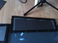
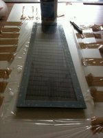
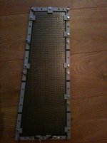
first look at the wire variant, it looks ugly as hell because i could not stretch them proper, i had a jig for a SMGA but because i decided to make a gap of 1mm between rows instead of the 1.5 magnepans uses, it would ofcourse not align... did not feel like making a new jig. also even with a jig its hard, i can align the midle part perfect , but the loops at the end. its hard to get it of the jig without screwing everything up.
well at least the sensitivity is way way higher. so it seems, i did not even ad the push pull.. well i let it dry for an hour or so and try adding the backside with the other magnets. migth have to increase spacing mylar magnets for the backplate because the wires with a diameter of 0.5 are glued on the mylar so closer to the backplate , it will slam iagainst that plate first.
a planar bass panels would be insane with wires and verry thin neo''s i recon. huge spacer distance, you could make a long trow 🙂
Hi,
Push pull makes no sense in magnetic planars are the field is in the wrong direction.
Repelling is the only way to get an ~ planer field for the diaphragm motion.
Magnets must be chosen carefully, typical magnets used for speakers are useless,
they are typically relatively high B and Low H, (hence the typical shape), you want
highest H and hang B, it doesn't really matter in a typical magneplanar arrangement.
Typical ceramic bar magnets magnetised across the face should be magnetised
across the width for more H and used edge on, not flat, to the diaphragm.
rgds, sreten.
o boy i was wrong, its hard to remember sound intensity, try listen to a sound during the day and then listen to it again during the night, when there is hardly any sound. or right after you woke up, ur ears works best in the morning!
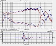
Well ok after measurements this is the result.
the Blue line is the version with a magnet gap of 3 mm and 3 mm 40 micron thick foil as conducter. in push pull. resulted resistance was 2.2 Ohm
red is magnet gap of 1 mm, and wire of 0.5mm dia and a total resistance of 2.4 Ohm , this could translate to 0.5 db or something in less eficiency because of the 0.2 ohm higher resistance. (doubt it even)
few thing are cleary seen.
1. the foil does not play softer then the wire., tits even a little bit louder.
2. frequency repsonce with foil extends, this could be because of all the glue crap used with wires.
3.resonance fequency changed, also because of the glue, is my guess.
4. the wires has more distortion in the lower octaves, its not much but its something.
5. LF response is better with the foil, this could be because the peak of the resonance lies higher and so it lifts the LF a bit.
6. the foil sounded better. less.... well wobbly or something a bit more controlled ?
still this could be all tension of the mebrane effects , that the higher resonance made it bit more punchy at frequencys he can deliever more easy then say the 40 hertz resonance of the wire setup. even so the impulse response from the foil type looks better to, if i interper this correctly
Attachments
Last edited:
Hi,
Push pull makes no sense in magnetic planars are the field is in the wrong direction.
Repelling is the only way to get an ~ planer field for the diaphragm motion.
Magnets must be chosen carefully, typical magnets used for speakers are useless,
they are typically relatively high B and Low H, (hence the typical shape), you want
highest H and hang B, it doesn't really matter in a typical magneplanar arrangement.
Typical ceramic bar magnets magnetised across the face should be magnetised
across the width for more H and used edge on, not flat, to the diaphragm.
rgds, sreten.
across the face is that the same as trough thickness ? and why edged on ? if you look at my femm pictures looks like i create a stronger field in the gap while magnets lie flat?
oh i did try with and without the push pull. and as expected 6dB more efficiënt with push pull.
Last edited:
WrineX,
Wow. You have done a lot in just a couple of days.
One trick that might help you to install the wire would be to run a DC current through it, which should hold it in place, centered between the magnets and with some pressure against the membrane. Sorry that I didn't mention that sooner.
Was the wire also aluminum?
Your wire and your foil have different cross-sectional areas, which gives them different resistances per unit of length, and different masses and weights.
Your foil's cross-sectional area is 0.040 mm x 3 mm = 0.120 mm².
Your wire is 0.5 mm diameter which gives 0.196 mm².
For aluminum wires and foil strips:
Ω/m = 0.026 / mm²
your foil's Ω/m = 0.217 Ω/m
your wire's Ω/m = 0.133 Ω/m
In order to have the same mass and resistance per meter as the foil, the wire would need to have the same cross-sectional area, 0.12 mm², i.e. a diameter of
d = 2√(0.12/π) = 0.391 mm = wire diameter needed to get 0.217 Ω/m
To get 4 Ohms with one piece of aluminum that has a cross-sectional area of 0.12 mm², the length would need to be
L = 4 Ω / (0.217 Ω/m) = 18.4 m
There is a lot of discussion about the wire and foil and glue, etc, on The Planar Asylum group.
Cheers,
Tom
Last edited:
Thx for the nicely layout calculations, i did something similair but 🙂 i came up with 0.028 ohm/M / mm2, but ur correct to make it complete fair i should had the same crosssection. weird enough the measured results was only 0.2 ohm difference.
would be so nice to have a super small test setup with same magnet layout with wire and foil and same crosssection. 🙂
i do have some 5 mm times 40 micron foil wich will end up in crossection of 0.2mm2 the wire with the 0.5 diameter ends up in a crossection of 0.1963mm2 . as close as it gets i gues ?
only stupid thing is, the foil is 5 mm width, im not sure if i have to make the gap 5 mm as well. that would screw up the magnet strength in the gap. i could let 1 mm on eacht side hang above the magnet, but then not everyhting is in the strongest field..... aaa problems
will take a look at the asylum as well. THX for ur help!
Last edited:
AAah im dumb...
oki forgot some things
the wire version had to runs between the magnet to reach 2.4 ohm. The foil version had in one run 2.2 ohm ,i added another run on the back of the mylar in series, so it ended up with 4.4 then took the measurements
the wire one ended with 2 runs, on only 2.2 ohm so i added a resistor to get 4.4 . but ofcourse this leads to the fact i wasted almost half the power, that whas not in the magnetic field.
I removed 2 turns from the wire panel, now it has the same length of coil as a 5mm foil type.
im going to measure the wire panel tomorow again without the resistor, i then clean the mylar remove al this crap and refoil it with the 5mm width foil, it should end up with the same resistance of conductor between the magnets, not outside it 🙂 then i have a comparison.
all the wasted time again 🙂 typical a project of mine
Last edited:
across the face is that the same as trough thickness ? and why edged on ? if you look at my femm pictures looks like i create a stronger field in the gap while magnets lie flat?
oh i did try with and without the push pull. and as expected 6dB more efficiënt with push pull.
Hi,
I'm considering B and H. Take a bar 5mm x 15mm x whatever length.
I'm saying magnets aligned along the 15mm, 5mm edge on, will
work much better than the typical magnets aligned across 5mm.
You get higher H and don't approach B limits.
Ceramic magnets need to to be very wide and flat to optimise
flux in a in the small gap of a speaker driver, and most bars
are magnetised across the smallest or largest dimension,
for purpose, here what you want is across the middle.
rgds, sreten.
Last edited:
across the face is that the same as trough thickness ? and why edged on ? if you look at my femm pictures looks like i create a stronger field in the gap while magnets lie flat?
oh i did try with and without the push pull. and as expected 6dB more efficiënt with push pull.
Hi,
I'm considering B and H. Take a bar 5mm x 15mm x whatever length.
I'm saying magnets aligned along the 15mm, 5mm edge on, will
work much better than the typical magnets aligned across 5mm.
You get higher H and don't approach B limits.
rgds, sreten.
One thing that seems to be an important design goal is to minimize the mass of the conductors. Magnepan has hinted about that (quite strongly), on the planar asylum.
Oh, before I forget, here is a link to one post about foil for planar speakers, from the first time I thought about it:
RE: "If we replaced the wire with foil that had 1/4th the mass and 4X the resistance per inch" ... - tom_gootee - Planar Speaker Asylum&
I think that I would try to figure out what maximum sustained amplitude of current I wanted them to be capable of handling (based on a rated max power and impedance), and find out what temperature the membrane could handle safely, and then try to calculate the smallest cross-sectional area that would not violate the temperature constraint when carrying the desired current. Then I guess you might need to cut your foil, the hard way (lengthwise).
If you don't purchase some different foil, for that, then you might only want to consider using widths that divide evenly into 5 mm, such as 2.5mm, 1.67mm, 1.25mm, and 1mm.
I once did find out how to calculate the temperature rise of any size wire, given the current and the wire size and material type. It's not an exact science, the way I did it, because there are de-rating factors from the "free air" conditions, for things like enclosed spaces and number of wires in a bundle, and insulation type and thickness. The nasa.gov website had some very useful stuff, for calculating the temperature rise of conductors.
Anyway, it would probably be better and quicker to just cut some different foil widths and test them. If you had some speakers with the same impedance you are designing toward, you could just put the foil in series with the speaker wire and play something at the maximum volume you would probably ever listen, and see what happens. Maybe even attach the foil to a piece of the membrane material, maybe even with the material under tension (so you would know if it got soft-enough to fail under tension).
------
In Figure 7.3 at
http://www.anixter.com/content/dam/Anixter/Guide/11H0001X00-Anixter-WC-Technical-Handbook-EN-US.pdf
we see that a cable with one COPPER conductor of AWG 26 (roughly equivalent to your foil's cross-sectional area of 0.12 sq mm. i.e. 0.39mm diameter) can carry 5 Amps RMS, if a temperature rise of 35 deg C is allowed.
And since they are talking about "cable" (i.e. with insulation), a bare one could probably carry more, with a lower temperature rise.
But I don't know how that compares with aluminum. Aluminum might be 50% worse, in terms of temperature rise.
Anyway, I think that most music's average power will probably be less than 20% of the rated max power of an amp, even with the volume turned up "extremely loud". (I just ran an LT-Spice simulation with a power amp model, with input from a WAV file of AC/DC's "Highway to Hell", and during the intro, when both the guitar and drums play, albeit somewhat intermittently, the output power hits peaks of 400 to 550 Watts but the average power is only 6 Watts. That was with RLC models of 8-Ohm speakers and crossovers. So it might be significantly more with lower-impedance speakers.)
So it SEEMS like it would probably be safe to use any practical foil width, or probably at least down to 2 mm and probably even smaller.
If you are wanting to use a smaller foil width, then the best way would be to test it, with continuous DC current, to see how much the temperature rises (which also depends on the ambient temp). That would then require finding out what the maximum average music power might be. So a "more practical" test might be to use music through it.
------
EDIT: Here is a link to a post where there are equations for determining if a number of parallel runs of foil will let you arrive at a particular resistance, for the amplifier to see. You can also use them to solve for the thickness and width needed.
http://db.audioasylum.com/mhtml/m.h...wmessage=&sort=score&sortOrder=DESC&forum=mug
You can click on "All" at the top of that page, to read the whole thread. The rest of the thread is very interesting (much more interesting than that one post).
I noticed that someone there says that "Magnepan's foil" is 0.025 mm x 3.175 mm. (But on my MG-12 tweeter section, it is 2.5 mm wide.)
Cheers,
Tom
Last edited:
Actually, it looks like you need to double the total resistance, anyway. So you should probably just cut your foil in half, to get a 2.5 mm width.
That should increase the sensitivity, as well as the dynamic abilities. I guess "by how much" might depend on how the mass of the total length of the 5mm foil plus the mass of the membrane compares to the mass of the 2.5 mm foil plus the mass of the membrane, except it's probably not the whole membrane mass, since the edges can't move (but neither can the ends of the foil).
That should increase the sensitivity, as well as the dynamic abilities. I guess "by how much" might depend on how the mass of the total length of the 5mm foil plus the mass of the membrane compares to the mass of the 2.5 mm foil plus the mass of the membrane, except it's probably not the whole membrane mass, since the edges can't move (but neither can the ends of the foil).
THanks gotee for all the links! i ways searching the asylum already but they have a verry limited search ability i could not find the thread you mentioned. so im gone do some reading 🙂
Gotee i could indeed drop the resistance , but for now i just want to see the diference, so i can decide go wire or go foil. and go push pull or not. the last one is kind of decided, who does not like +6dB 🙂
Gotee i could indeed drop the resistance , but for now i just want to see the diference, so i can decide go wire or go foil. and go push pull or not. the last one is kind of decided, who does not like +6dB 🙂
@ Gootee
nice discussion about the half the crossection and replace it with foil. only thing is rating goes down as well, hopefully no smoking tweeters there?
nice discussion about the half the crossection and replace it with foil. only thing is rating goes down as well, hopefully no smoking tweeters there?
I think the 2.5 mm foil should be OK. But you can test it, to be more certain.
You should also install fuses in the speakers.
You should also install fuses in the speakers.
- Status
- Not open for further replies.
- Home
- Loudspeakers
- Planars & Exotics
- trying to get around FEMM and a push pull magneplanar