That is weird! A cascode with feedback to the upper grid, and somewhat mismatched triodes in the lower half.
Now I wish I could read German. Correction: the text appears to be a user manual, not a circuit description, so less useful.
Now I wish I could read German. Correction: the text appears to be a user manual, not a circuit description, so less useful.
Last edited:
One thing to notice about this circuit is the way the negative bias for the output pentodes is produced: a resistor in the negative feed from the PSU (R51 200ohms). It is a form of cathode bias, but diluted by all the other valves in the set. Similar to what was often done in a battery set.
This allows application of negative feedback to the cathode from the OPT output winding.
This allows application of negative feedback to the cathode from the OPT output winding.
Last edited:
The basket colour on the FR suggests to me it may be italian (ATM can't recall the brand name), the tweeter is an older aperiodic, shallow Isophon, the most desirable version. It will have a date-code on it which will help establish the age.
The OPTs on this unit are fairly large for the genre.
dave
The OPTs on this unit are fairly large for the genre.
dave
Hi Hush....finally had a chance to look at the pics and other comments regarding your Kuba.
I can tell you that your chassis is different from the three or four Kuba sets I own. I actually use them more to salvage the PTs and OPTs and tubes--quite often Telefunkens, Valvos etc--than to rebuild them.
I just finished a Loewe-Opta (another German console radio maker) and to put it bluntly, the ubiquitous German designs of the period are labour intensive to troubleshoot due in no small part to their overly convoluted layout and design and propensity for badging dissimilar chassis with the same model names.
I've done a few full-bore rebuild-restorations for friends and would warn you they are rife with tribulation especially since relevant and accurate schematics are so difficult to locate even at Radio Museum...one of the best sources for mainland European made sets.
I am assuming you've tested the output and pre-amp tubes.
One of the 6BM8s could be substantially weaker than the other. Also swap the two 6BM8s and see if the low-output on the right channel switches to the left. If they test within the ball-park of one another as do both sides of the Double Triode you should be ok to move on.
Spray the switches, volume, balance, tone pots and contacts on the set with Deoxit...they are also notorious for getting gummed up, dirty and intermittent and could be responsible for the difference in channel output levels.
In my experience the OTs and OPTs are rarely a problem....so I'd head for the caps, of which the brown mica "Wimas" are almost guaranteed to be shot.
I'd also replace all the paper wax caps in the set...Ditto...the can electrolytics.....
Then bring it up slowly on an isolated AC power supply to see what you're getting in terms of equal output on both channels.
Better-Worse-Same?
Those results will determine if you'll have to go deeper in terms of debugging.
Fellows like Eli, DF96, grommeteer have the all technical expertise and knowledge to lead you further down the path if the preliminary debugging doesn't sort the set out. All I've got to offer is dirty finger-nails and and my hard-won experience working on these "Teutonic Terrors"
Attachments


Last edited:
The basket colour on the FR suggests to me it may be italian (ATM can't recall the brand name), the tweeter is an older aperiodic, shallow Isophon, the most desirable version. It will have a date-code on it which will help establish the age.
The OPTs on this unit are fairly large for the genre.
dave
Hi Dave...The purple basket FR speakers in my Kuba's are marked TT....never did figure out the name of the company or the country of manufacture😕
BTW Hush you might also try the good folks at http://www.antiqueradios.com/....lots of expertise with these old consoles there too🙂
....never did figure out the name of the company
Looking at my picture stash, IREL, i'd have to dig deep into some old, old eBay ads to get more.
dave
Looking at my picture stash, IREL, i'd have to dig deep into some old, old eBay ads to get more.
dave
No need...yes they are IRELs......😀
FWIW, I think the fact that the "iron" is decent is quite important. A SE pentode mode 6BM8 in each channel is truly straight forward. Any number of the members on this board can whip up a reasonable circuit to exploit the "iron". Certainly, the EZ81/6CA4 B+ rectifier is no slouch. As a for instance, a 0B2 glow tube could be used to regulate the g2 B+ of the "finals".
When you will investigate the dead channel issue, before swapping output tubes from one channel to the other, check the coupling caps for leakage (by measuring with a DC voltmeter the voltage across the caps). If a cap leaks, the screen on the pentode gets a high positive voltage, the anode current goes high and the OT transformer primary suffers (or burns)
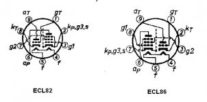
ECL 82 pin-out is different from ECL86
George
ECL 82 pin-out is different from ECL86
George
Attachments
New development - changed power rails and debug amp
Hello everybody,
Sorry dropping the project for a while.
Last couple of days I finally spent some time in restoration and debugging the console.
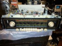
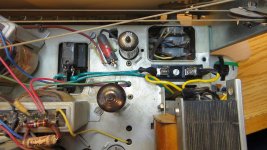
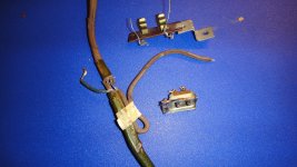
What I have done – I’ve started rebuilding completely the power supply rail - seems that the power transformer either have been replaced or some gimmicky repair job(s) have been done, extremely dangerous! The transformer have been mounted pressing the 110V cable and the heat “ate” the insulation to almost running bare 110V to transformer’s enclosure (see photo 5).
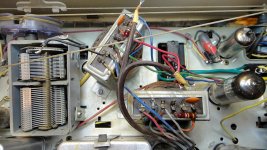
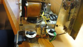
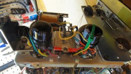
I’ve rebuild all the wiring, installed new fuse holder (see how was done before on photo 5), replaced both the can caps (50uF/350V) with Samsung 150uF/400V and made new enclosure for standard 3-pin female power connector, grounding the chassis to power ground (see photos 1, 2 and 3).
I also broke-in all the pots and switches with good contact/silicon spray.
I run standard Line-In (CD-player) with nice jazz CD and power it up. The sound appeared loud and clear all the way! AM with internal ferrite antenna works absolutely clear IN THE BASEMENT, so no complains about AM at all.
The bad – I still have FM dead (no hissing noise at all) and I still have one of the channels distinctively quieter than the other one.
I started with troubleshooting the amp as that would be the main use anyways.
Please refer to the “imperial_j611k_sch.pdf “file from the thread (attached again below) from now on – it is NOT the exact schematic, but seems to be close enough to troubleshoot.
What I have checked and done:
- swapping the tubes makes the things even slightly worse (meaning – the quieter channel kept being quieter, but louder channel become more loud, very little, but I can tell the difference – e.g. – tubes are fine.
- if I remove the ground connection from the speakers (pin 1 and 6) and leave speakers in series (fed between pins 3 and 8) – the output it equal (the way it should be).
I’ve checked the WHOLE passive rail with BASS/TREBLE and some funky corrections (everything west of the triode of ECL86 on the schematic – pots, switches and passive components) with signal-generator and scope – everything works fine, all controls and balance work.
I’ve decided to go to the back end – pentodes of ECL86:
- replaced the 470pF caps (C66 and C79) – no difference
- replaced the 10nF caps (C65 and C78, actually – 3.3nF on the board) – no difference
- all surrounding resistors are fine and exact
I’ve checked the DC on the anodes – seems that the problem is somehow there – voltages are as follows:
- main power DC (from rectifier) – 221V
- same DC is on the OTs – pin “rt” (rot = red)
- on the quieter channel – anode of the pentode (pin 6) has 204V on power up and goes slightly down do 201V after warming up.
- on the louder channel – anode of the pentode (pin 6) has 218V on power up and stays 218V, EVEN after warming up.
I may have missed some caps or other components to check on the back-end as the schematic is not exact and the mess on the board is big enough, but I can’t see any reasonable explanation why the DC is different. So far, excluding obviously shot big-can electrolytic caps – every single passive component I’ve checked is dead on the value and I can’t see any other electrolytic cap to change...
I’ve even swapped the output transformers (see photo 5) – the result is the same, but the power voltage rose up to 230V, of course – quieter channel still has lower voltage on the anode, but is 3-5V higher before the swap. Go figure now...
I don’t have extra tubes to play further, but I feel that I reached dead end for now.
Any ideas would be appreciated, guys, thanks in advance!😀
Hello everybody,
Sorry dropping the project for a while.
Last couple of days I finally spent some time in restoration and debugging the console.
What I have done – I’ve started rebuilding completely the power supply rail - seems that the power transformer either have been replaced or some gimmicky repair job(s) have been done, extremely dangerous! The transformer have been mounted pressing the 110V cable and the heat “ate” the insulation to almost running bare 110V to transformer’s enclosure (see photo 5).
I’ve rebuild all the wiring, installed new fuse holder (see how was done before on photo 5), replaced both the can caps (50uF/350V) with Samsung 150uF/400V and made new enclosure for standard 3-pin female power connector, grounding the chassis to power ground (see photos 1, 2 and 3).
I also broke-in all the pots and switches with good contact/silicon spray.
I run standard Line-In (CD-player) with nice jazz CD and power it up. The sound appeared loud and clear all the way! AM with internal ferrite antenna works absolutely clear IN THE BASEMENT, so no complains about AM at all.
The bad – I still have FM dead (no hissing noise at all) and I still have one of the channels distinctively quieter than the other one.
I started with troubleshooting the amp as that would be the main use anyways.
Please refer to the “imperial_j611k_sch.pdf “file from the thread (attached again below) from now on – it is NOT the exact schematic, but seems to be close enough to troubleshoot.
What I have checked and done:
- swapping the tubes makes the things even slightly worse (meaning – the quieter channel kept being quieter, but louder channel become more loud, very little, but I can tell the difference – e.g. – tubes are fine.
- if I remove the ground connection from the speakers (pin 1 and 6) and leave speakers in series (fed between pins 3 and 8) – the output it equal (the way it should be).
I’ve checked the WHOLE passive rail with BASS/TREBLE and some funky corrections (everything west of the triode of ECL86 on the schematic – pots, switches and passive components) with signal-generator and scope – everything works fine, all controls and balance work.
I’ve decided to go to the back end – pentodes of ECL86:
- replaced the 470pF caps (C66 and C79) – no difference
- replaced the 10nF caps (C65 and C78, actually – 3.3nF on the board) – no difference
- all surrounding resistors are fine and exact
I’ve checked the DC on the anodes – seems that the problem is somehow there – voltages are as follows:
- main power DC (from rectifier) – 221V
- same DC is on the OTs – pin “rt” (rot = red)
- on the quieter channel – anode of the pentode (pin 6) has 204V on power up and goes slightly down do 201V after warming up.
- on the louder channel – anode of the pentode (pin 6) has 218V on power up and stays 218V, EVEN after warming up.
I may have missed some caps or other components to check on the back-end as the schematic is not exact and the mess on the board is big enough, but I can’t see any reasonable explanation why the DC is different. So far, excluding obviously shot big-can electrolytic caps – every single passive component I’ve checked is dead on the value and I can’t see any other electrolytic cap to change...
I’ve even swapped the output transformers (see photo 5) – the result is the same, but the power voltage rose up to 230V, of course – quieter channel still has lower voltage on the anode, but is 3-5V higher before the swap. Go figure now...
I don’t have extra tubes to play further, but I feel that I reached dead end for now.
Any ideas would be appreciated, guys, thanks in advance!😀
Attachments
-
 Receiver - OTs Before.JPG499.5 KB · Views: 104
 -
 Receiver - New Power - Side.JPG368 KB · Views: 96
 -
 Receiver - New Power - Side 2.JPG357.4 KB · Views: 97
 -
 Receiver - New Power - Top.JPG428.8 KB · Views: 108
 -
 Power Components - Before.jpg673.2 KB · Views: 70
 -
imperial_j611k_sch.pdf581.1 KB · Views: 95
Last edited:
looks like ecc85 is the fm tuner.
check all the switch contacts, check r5 for 470 ohms
check R1 for 150 ohms
pull tube and check pin 6 for 90+ volts
check all the switch contacts, check r5 for 470 ohms
check R1 for 150 ohms
pull tube and check pin 6 for 90+ volts
- Status
- Not open for further replies.
- Home
- Amplifiers
- Tubes / Valves
- Kuba Serenade Stereo Console question.