Alu Heatsinks
Fredlock,
i got them from Tayda. They are pre Taped for 3mm as well. Got the original link for Tayda from PMI.🙂
Heatsink - Hardware
Fredlock,
i got them from Tayda. They are pre Taped for 3mm as well. Got the original link for Tayda from PMI.🙂
Heatsink - Hardware
Thanks Rick. Transistor ZVN2106A is backorder from Mouser. Now, I have to order it from Newark which I have to pay another shipment. 😡 If I only knew, I could have ordered everything from Newark for one single shipment.
I should have some spares from when I was making the kits for a few people who don't have good (cheap) access to the usual distributors. Last time I mailed a few parts in the US, postage was $1.17. Not sure how many are left, but I can also add a few to my next Newark order if I don't have enough. I have an order going to Newark/Farnell about Wed, I think.Thanks Rick. Transistor ZVN2106A is backorder from Mouser. ..
Any reason why mica washers are specified for the MOSFETS? I haven't bothered insulating the transistors since each one has its own heatsink. Anyone see a problem with this?
I usually specify insulators for heatsinks. If someone wants to leave them off, at least they have been warned, so to speak... 😀Any reason why mica washers are specified for the MOSFETS? I haven't bothered insulating the transistors since each one has its own heatsink. Anyone see a problem with this?
Actually, any kind of insulator would do the job, I did not intend to specify mica. Main benefit is electrical isolation from the heatsink in case of shorts, for example when someone is setting or checking the pass transistor voltage drop.
For best results, you should at least check this with the amp as a load, and make sure the positive and negative rails are the same. This normally means when installed in the chassis, with limited space, so a short is a definite possibility.
You may have also noticed there is a fuse cover in the BOM, although most of my pics do not show one installed... 😉
All good reasons... you've talked me into sticking a washer / silpad on it.
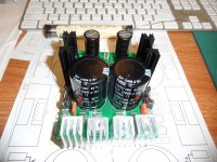
Here's a photo of my completed PSUs, incl. fuse covers (I followed your BOM to the letter... ;-)
Here's a photo of my completed PSUs, incl. fuse covers (I followed your BOM to the letter... ;-)
An externally hosted image should be here but it was not working when we last tested it.
You sure lay on lots of lead!All good reasons... you've talked me into sticking a washer / silpad on it.
Here's a photo of my completed PSUs, incl. fuse covers (I followed your BOM to the letter... ;-)
An externally hosted image should be here but it was not working when we last tested it.
Only on the faston tabs. I had one pull through previously when pulling off a particularly tight connectors.
A cold solder joint can cause that, but one of the main reasons is holes that are not plated through. Without hole plating, solder will not fill the hole, and the pads alone cannot possibly hold that much force by themselves.Only on the faston tabs. I had one pull through previously when pulling off a particularly tight connectors.
The solder in the hole makes the connection between solder on top and on the bottom. Just like the center part of an I-beam in building construction. Take that away, and there is not much strength left in the joint.
OK, So What am i doing Wrong Here. I have a 120V Pri traffo With 2 30VAC Secondaries.
I only have 1 working VSSA module at present & 1 Cap Multi. So i hook up one Sec (blue/Grey) to AC1 & AC4. I also have 1 green 'Screen' Wire, so i put it on AC2. With NO load i am getting only 21VDC at Fuse. I can adj the output to be within .5V of this reading.
The AC across AC1&2 is still 32.5VAC. So why is DC voltage so Low?
The way you have it hooked up, you are splitting the secondary AC voltage. Better if you use both secondary windings, one per rail. In that case, you should see around 30 * 1.414 ~ 42V on each rail (plus about 5% at no load.)OK, So What am i doing Wrong Here. I have a 120V Pri traffo With 2 30VAC Secondaries.
I only have 1 working VSSA module at present & 1 Cap Multi. So i hook up one Sec (blue/Grey) to AC1 & AC4. I also have 1 green 'Screen' Wire, so i put it on AC2. With NO load i am getting only 21VDC at Fuse. I can adj the output to be within .5V of this reading.
The AC across AC1&2 is still 32.5VAC. So why is DC voltage so Low?
If you have 4 wires from the secondary side (they should be color-coded), you should always connect one sec. to AC1-AC2, and the other secondary to AC3-AC4. If the transformer windings are marked with a black dot on one end, then this wire should be connected to AC1 and AC3, respecively, for the two secondary windings.
I do this with the fuses out, and then I check the DC voltage at the fuse sockets, and make sure I have about 1.4-1.5 times the nominal secondary voltage, both positive and negative rail.
There are no stupid questions, just stupid answers.... (especially true of Audio) 😀Thank You, & Yes i really am that stupid. Sounds Great!
So far we have seen PMI's masterpiece and one other completed project (albeit slathered in lead ;-)
So has anyone else got pics to share?
So has anyone else got pics to share?
Here's a pic of one of mine pushing a Honey Badger today. I had it up to 47.8V rails and it didn't even get warm.
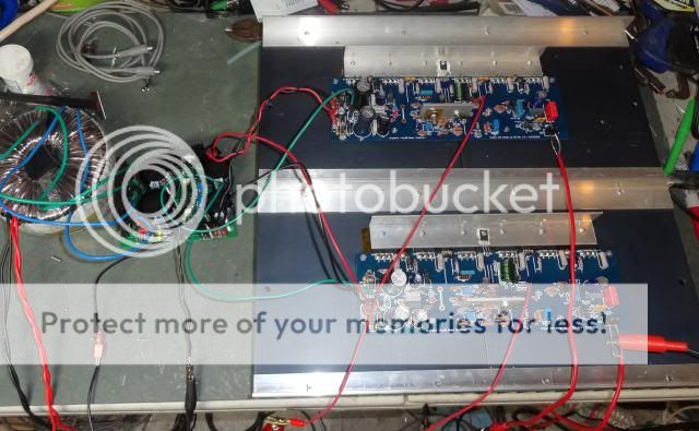

Here's a pic of one of mine pushing a Honey Badger today. I had it up to 47.8V rails and it didn't even get warm.
 🙂
🙂edit:
I can get warm, trust me... The intent was to cover most conventional Class A-B amps up to 100W/channel. Did you let the Honey Badger amp run for a while?
Last edited:
- Status
- Not open for further replies.
- Home
- Amplifiers
- Power Supplies
- Finished capacitance multiplier