Q6 and Q8 should be identical.
Does this mean, Q6 and Q8 act as drivers and higher Hfe is prefarable? Besides these ones (except Q13 of course) act as switching transistors and Hfe spec is not considerable at all?
Q6 and Q8 are the Tringle's governors, and they need to be as perfectly matched as possible in order to achieve perfect error correction. For them as for the other transistors of the Tringlophone, the absolute Hfe is unimportant, it just needs to be sufficient.Does this mean, Q6 and Q8 act as drivers and higher Hfe is prefarable? Besides these ones (except Q13 of course) act as switching transistors and Hfe spec is not considerable at all?
For them as for the other transistors of the Tringlophone, the absolute Hfe is unimportant, it just needs to be sufficient.
For example, can you consider ~50 of Hfe value is sufficient?
Plain 2N2219's are rated at 30V. Is there any Vceo rating constraints for these ones for Vs=>30V conditions?
I'm working on Darlington Circlophone and I have finished PCB's. Same time, I'm also collecting some Soviet era transistors for next tringlophone build which consist of some MEV 2n2904/2n2912(non-A)'s. That's why I'm asking too much about these ones.
Last edited:
It's OKFor example, can you consider ~50 of Hfe value is sufficient?
Vceo=30V is quite sufficientPlain 2N2219's are rated at 30V. Is there any Vceo rating constraints for these ones for Vs=>30V conditions?
They should work alrightI'm working on Darlington Circlophone and I have finished PCB's. Same time, I'm also collecting some Soviet era transistors for next tringlophone build which consist of some MEV 2n2904/2n2912(non-A)'s. That's why I'm asking too much about these ones.
Hello Elvee!
I currently have a Circlophone module and I really want to make a Tringlophone Module!
I'm going to throw me to draw a PCB but I have some questions before.
The transistors Q2, Q4, Q6, Q8 (2N2905) they may be replaced by BD140?
Regards!
I currently have a Circlophone module and I really want to make a Tringlophone Module!
I'm going to throw me to draw a PCB but I have some questions before.
The transistors Q2, Q4, Q6, Q8 (2N2905) they may be replaced by BD140?
Regards!
You're welcomeHello Elvee!
I currently have a Circlophone module and I really want to make a Tringlophone Module!
Yes, as long as they are identical, no problem: the circuit is open loop and will tolerate practically any device. To allow the tringlotron effect to work properly, the devices should be identical (it will also work with heterogeneous devices, but with no or diminished compensation; could be interesting too, for people fond of "colorations")I'm going to throw me to draw a PCB but I have some questions before.
The transistors Q2, Q4, Q6, Q8 (2N2905) they may be replaced by BD140?
I started drawing a printed but I need some information for the size of circuit components.
What is power resistors used?
And in particular:
R1 => 2W
R28 =>??
R8 =>,
R9 =>,
For capacitor C5 (4700 uf) I have put 10 capacitors (470 uf) in parallel because I make space but I do not know if the result will be the same.
Thank you!
What is power resistors used?
And in particular:
R1 => 2W
R28 =>??
R8 =>,
R9 =>,
For capacitor C5 (4700 uf) I have put 10 capacitors (470 uf) in parallel because I make space but I do not know if the result will be the same.
Thank you!
I was on to draw an alternate layout or modify Counter Culture's layout but never got a chance. Hope you build this extraordinary amplifier and share your impressions here. I remember you have good speakers.
Actually 1W would suffice, but going larger does no harm.I started drawing a printed but I need some information for the size of circuit components.
What is power resistors used?
And in particular:
R1 => 2W
1W is the typical rating for this functionR28 =>??
Let's say 0.5W: your tweeters will be fried well before you reach that levelR8 =>,
R9 =>,
For capacitor C5 (4700 uf) I have put 10 capacitors (470 uf) in parallel because I make space but I do not know if the result will be the same.
Paralleling capacitors does no harm, quite the opposite. Try to keep the composite compact.
Hello Elvee!
I have finished the design of my circuit but I still have to check it and then I 'adapts to the components (capacitors) a little smaller and I'll win a little space. Map of my printed circuit measures 8x8 cm now.
Two or three questions before completing this work and offer my printed circuit on this forum.
Q2, Q4, Q6, Q8 => BD140 (OK)
but:
Q9, Q11 => BD140: it's good?
Q10, Q12 => BD139: it's good?
Meanwhile along the implementation of the circuit provided for transistors TIP3055 kind.
Thank you!
Attachments

Last edited:
Very neat and compact: a real jewel of a circuit, bravo!Hello Elvee!
I have finished the design of my circuit but I still have to check it and then I 'adapts to the components (capacitors) a little smaller and I'll win a little space. Map of my printed circuit measures 8x8 cm now.
They are perfectly OKTwo or three questions before completing this work and offer my printed circuit on this forum.
Q2, Q4, Q6, Q8 => BD140 (OK)
but:
Q9, Q11 => BD140: it's good?
Q10, Q12 => BD139: it's good?
Meanwhile along the implementation of the circuit provided for transistors TIP3055 kind.
Thank you!
I have some better position from any component at a time (the look is important too).
I will offer this circuit this weekend.
Regards!
I have some better position from any component at a time (the look is important too).
I will offer this circuit this weekend.
Regards!
New design!
Hello everyone!
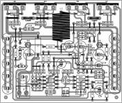
I drew another version of the circuit because the first included too long tracks
I do not know if this version is correct, but I submit. I still have to check if all the connections are correct.
The design of the circuit of this amplifier is very difficult.
This new version measuring 8.6 x 7.3 cm.
If you think this kind this circuit can cause problems, let me know.
Regards!
Hello everyone!
I drew another version of the circuit because the first included too long tracks
I do not know if this version is correct, but I submit. I still have to check if all the connections are correct.
The design of the circuit of this amplifier is very difficult.
This new version measuring 8.6 x 7.3 cm.
If you think this kind this circuit can cause problems, let me know.
Regards!
Attachments
Hello Project16,
Nice work. Here something that I can say on first sight:
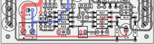
* I think it is better to use a single footprint for output capacitor rather parallelling them on pcb. Parallelling caps can be made on the fly depending on builder preference.
* Output coil footprint seemed to me too big for a 1.8uH . If we use thick wire, then we can overlap windings, right?
Regards.
Nice work. Here something that I can say on first sight:
* I think it is better to use a single footprint for output capacitor rather parallelling them on pcb. Parallelling caps can be made on the fly depending on builder preference.
* Output coil footprint seemed to me too big for a 1.8uH . If we use thick wire, then we can overlap windings, right?
Regards.
Ok Terranigma I'll change around these!
Elvee I have a question:
What amperage capacitor C5 (4700uf/25v) must support?
Thank you!
Elvee I have a question:
What amperage capacitor C5 (4700uf/25v) must support?
Thank you!
It sees the load current, less than 1.5A rms. Btw, I see nothing wrong with paralleled capacitors: the composite will normally have better characteristics than a single one of larger value, and if you opt for the larger one anyway, you can leave the unused spaces empty. Doing the opposite will result in something messierOk Terranigma I'll change around these!
Elvee I have a question:
What amperage capacitor C5 (4700uf/25v) must support?
Hello Elvee!
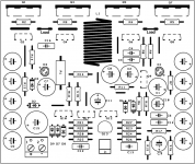
I have finished the design of my circuit board that contains no error and I can map a 8.5 x 7.1 cm with standard components (that is very tight).
I have a doubt about the input of the amplifier, the +32 v is connected as shown on my picture?
Thank you!
I have finished the design of my circuit board that contains no error and I can map a 8.5 x 7.1 cm with standard components (that is very tight).
I have a doubt about the input of the amplifier, the +32 v is connected as shown on my picture?
Thank you!
Attachments
Congratulations, it is no mean feat!Hello Elvee!
I have finished the design of my circuit board that contains no error and I can map a 8.5 x 7.1 cm with standard components (that is very tight).
Yes, it is: with this polarity of transistors, the ground is referenced to the positive side of the supplyI have a doubt about the input of the amplifier, the +32 v is connected as shown on my picture?
Arrays
C5: I would prefer the output cap array as 3 of 2200uF (or 4 of 1500uF), with these caps mounted as close as possible to each other.
P.S.
C15: A power cap array of 3 of 220u (or 3 of 270u) may boost the dynamic punch, so that may be a worthy experiment.
C5: I would prefer the output cap array as 3 of 2200uF (or 4 of 1500uF), with these caps mounted as close as possible to each other.
P.S.
C15: A power cap array of 3 of 220u (or 3 of 270u) may boost the dynamic punch, so that may be a worthy experiment.
- Status
- Not open for further replies.
- Home
- Amplifiers
- Solid State
- ♫♪--My little posh Tringlophone--♪♫