If output noise isn't an issue, this circuit could work.
For an input of about 400mVpeak (Most CD players) and an output of about 2Vpeak enough to drive most amplifiers, THD is in the order of 0.1% and noise in a 20KHz bandwith is about 30uVRMS (Calculated). Not so bad ah ? 😎
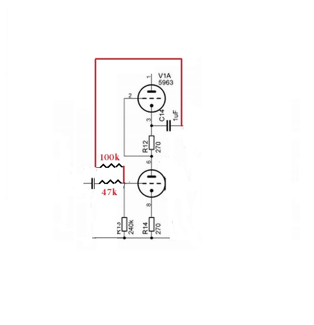
P.D. LTSpice don't allow pots, so both 50K resistors form a 100K volume pot.
For an input of about 400mVpeak (Most CD players) and an output of about 2Vpeak enough to drive most amplifiers, THD is in the order of 0.1% and noise in a 20KHz bandwith is about 30uVRMS (Calculated). Not so bad ah ? 😎
P.D. LTSpice don't allow pots, so both 50K resistors form a 100K volume pot.
Attachments

Autenator for input
Hi guys!
I'd bent the entrance R2/R3 = 22k/33k and that's it for output CD/DVD player!!😉
cheers!
Hi guys!
I'd bent the entrance R2/R3 = 22k/33k and that's it for output CD/DVD player!!😉
cheers!
Last edited:
If output noise isn't an issue, this circuit could work.
For an input of about 400mVpeak (Most CD players) and an output of about 2Vpeak enough to drive most amplifiers, THD is in the order of 0.1% and noise in a 20KHz bandwith is about 30uVRMS (Calculated). Not so bad ah ? 😎
P.D. LTSpice don't allow pots, so both 50K resistors form a 100K volume pot.
I would be interested to know how you calculated the noise.
Cheers
Ian
Looks like the thermal noise of the input attenuator, multiplied by the gain.I would be interested to know how you calculated the noise.
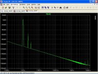
Total noise except valve noise, courtesy of LTSpice, ≈ 30μV RMS
From here
The Sound of Silence: Lowest-Noise Riaa Phono-Amps: Designer's Guide - Burkhard Vogel - Google Libros
Valve noise is bounded by Vn ≈ 28 μV RMS, so total noise is
eN ≈ √[(30μV)^2 + (28μV)^2] ≈ 41 μV RMS
Oops, sorry, the last time I did this calculation, I took most optimistic values for valve noise, about 6 μV RMS, I now assume the worst case scenario. 😉
BTW, S/N ratio of about 88 dB isn't so bad, right ? 😎
Total noise except valve noise, courtesy of LTSpice, ≈ 30μV RMS
Interesting, how did you coax that figure out of LTspice?
From here
The Sound of Silence: Lowest-Noise Riaa Phono-Amps: Designer's Guide - Burkhard Vogel - Google Libros
Valve noise is bounded by Vn ≈ 28 μV RMS, so total noise is
Burkhard openly admits he only considers shot noise. This means his figures are always optimistic. 28uV at the output of a stage with a gain of no more than 14 is an EIN of 2uV which is close to the best I have ever measured.
eN ≈ √[(30μV)^2 + (28μV)^2] ≈ 41 μV RMS
Oops, sorry, the last time I did this calculation, I took most optimistic values for valve noise, about 6 μV RMS, I now assume the worst case scenario. 😉
BTW, S/N ratio of about 88 dB isn't so bad, right ? 😎
Probably 3 to 6dB worse in practice but that's about right for a typical tube preamp. If you get below -80dBV you are doing well.
Cheers
ian
Interesting, how did you coax that figure out of LTspice?
LTSpice take account of thermal noise voltage density from all resistors in the circuit, then the software integrates this noise density and shows total noise. See attachment.
Burkhard openly admits he only considers shot noise. This means his figures are always optimistic. 28uV at the output of a stage with a gain of no more than 14 is an EIN of 2uV which is close to the best I have ever measured.
In 7.3 (page 96) Herr Vogel derives his own 3.06/gm "chestnut" for shot noise.
After that, at page 98, he introduces 1/f noise in a tricky way by eq.(7.7)
In 7.7 (page 102) Herr Vogel takes into account 1/f noise, and so does for further calculations/grafics.
It is always a questionable prediction, but this is the only one that I have. 😀
We can note that with a +B of 200V, about 100V for each triode section, the electron cloud is pretty large, so we can expect a reduction in shot noise.
Increasing +B we can reduce the number of electrons in the cloud, this can also increase valve linearity, at expense in an increase of shot noise.
At +B of about 350V, S/N ratio, measured by elektor laboratories (In the '80s), is about 86 dB. This is pretty consistent with calculations. 😎
BTW. The gain of proposed circuit is about x10, or 20 dB, so the input referred noise in a 20 KHz bandwidth, is about 2.8 μV RMS.
The ECC82 is not so noisy after all. 😉
Probably 3 to 6dB worse in practice but that's about right for a typical tube preamp. If you get below -80dBV you are doing well.
Cheers
ian
In my book, S/N ratio of 88 dB for a line stage is only acceptable in a 100 KHz bandwidth, but it is a matter of taste. 🙂
Attachments
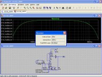
LTSpice take account of thermal noise voltage density from all resistors in the circuit, then the software integrates this noise density and shows total noise. See attachment.
Interesting because my version of LTspice will not do this. I get the plot same as you but how did you get the popo up box with the summary?? (see attachement)
In 7.3 (page 96) Herr Vogel derives his own 3.06/gm "chestnut" for shot noise.
After that, at page 98, he introduces 1/f noise in a tricky way by eq.(7.7)
In 7.7 (page 102) Herr Vogel takes into account 1/f noise, and so does for further calculations/grafics.
It is always a questionable prediction, but this is the only one that I have. 😀
I don't know if you have a different version of Vogel's book to the one I read but I am certain he said he did not know of a formula for calculating 1/f noise and then made some kind of guesstimate. However, a formula for tube noise including 1/f noise has been known for at least half a century. There is a very detailed treatment in the book "Amplifying Devices and Low Pass Amplifier Design" by E.M. Cherry and D.E Hooper (ISBN 67-29933). My copy is dated 1968 and it refers to works on tube noise written long before that.
We can note that with a +B of 200V, about 100V for each triode section, the electron cloud is pretty large, so we can expect a reduction in shot noise.
Increasing +B we can reduce the number of electrons in the cloud, this can also increase valve linearity, at expense in an increase of shot noise.
At +B of about 350V, S/N ratio, measured by elektor laboratories (In the '80s), is about 86 dB. This is pretty consistent with calculations. 😎
Do you have a reference to this Elektor article?
BTW. The gain of proposed circuit is about x10, or 20 dB, so the input referred noise in a 20 KHz bandwidth, is about 2.8 μV RMS.
The ECC82 is not so noisy after all. 😉
As I have said before, very few of the tubes I have measured have been better than 2uV EIN. 2.8uV is pretty tyipical in my book.
Cheers
Ian
Ahah!!! I just found you can get the integrated noise by using the control key and clicking on the trace. Excellent.
Cheers
ian
Cheers
ian
Interesting because my version of LTspice will not do this. I get the plot same as you but how did you get the popo up box with the summary?? (see attachement)
Run the noise simulation, with the cursor over "V(onoise)" press Ctrl and right clik, thats all.
Edit: Too late. 😀
I don't know if you have a different version of Vogel's book to the one I read but I am certain he said he did not know of a formula for calculating 1/f noise and then made some kind of guesstimate. However, a formula for tube noise including 1/f noise has been known for at least half a century. There is a very detailed treatment in the book "Amplifying Devices and Low Pass Amplifier Design" by E.M. Cherry and D.E Hooper (ISBN 67-29933). My copy is dated 1968 and it refers to works on tube noise written long before that.
The book of the link is the second edition, you know the old trick, second edition almost ever has more information, unfortunately I have only the first edition, and by Murphy's law, the link will be broken soon.
Thanks for the info, I'll do my best to obtain a copy of the book.
Do you have a reference to this Elektor article?
I have the entire article in PDF, is in Spanish, but if you want I can send to you a copy, send me a PM.
As I have said before, very few of the tubes I have measured have been better than 2uV EIN. 2.8uV is pretty tyipical in my book.
Cheers
Ian
You are a lucky man, I would make noise measurements, but I only have a pair of multimeters and an old scope.
Last edited:
You are a lucky man, I would make noise measurements, but I only have a pair of multimeters and an old scope.
That is exactly how I started off about 10 years ago. Then I got an audio milli-voltmer from eBay and later an HP distortion meter. Neither was a perfect instrument but it got me going. Later I got a Ferrograph test set on eBay and I still use that today.
Cheers
Ian
A piece of wire--
Is the most linear, low-noise Unity-Gain stage there is!
To be very honest, I cant see the point of adding this stage to the whole system,--just to render it so low gain....
Seems just a good way to add unnecessary distortion and noise to the signal....
--Thats just my simple and daft opinion!
Someone famous once said--Make it Simple--But No Simpler....
Success! 🙂
Just to recap all in 1 place, here's my original schematic:

and the proposed NFB modification:
So I got some metal film 1/4w resistors ordered and found the time this week to get my soldering iron out.
I made a rough mockup of the circuit board layout using photoshop

and plotted out the proposed NFB mod, as well as Ian's proposed 220uf bypass cap on the lower cathode resistor.

Here's the board ready for the work

I was worried about getting the resistors in on the front without it getting too crowded or messy, so I opted to install them to the back of the board as they're only thin and I have tall enough standoffs for the board


bypass caps will fit neatly on the front though with a little leg bending and glue to secure them

Sorted 🙂

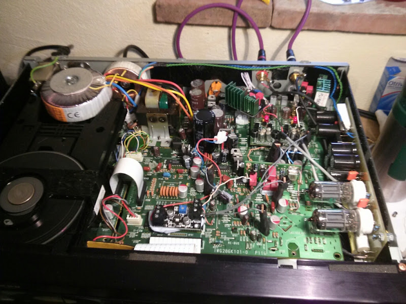
And it's all sorted and back in it's happy, crowded, messy place now (Marantz CD63 btw)

Here's a wider picture for context, from before the mod was made:
Has it done what I wanted?
Yes, it's perfect 😀
It's brought the amplitude down to what I'd consider within the normal range, still sounds really very nice indeed and as a bonus it seems to have also cleaned up a slight high pitched background noise I had before. I could just about make it out previously in very quiet sections of tracks when listening at high volumes and although very slight, it bugged me that I could hear it if I tried to. Now that noise has been reduced to inaudible compared to the music and I can only hear it if I pause the music and turn things up way past what would be bearable volumes. Now my silences are truly silent 🙂
Happy days!
Thanks guys for the help, especially Ian
I'm really pleased with the results and as with most of my ventures into DIY Audio, I've learned a fair bit along the way and found it really rewarding 🙂
cheers again,
James
Just to recap all in 1 place, here's my original schematic:
and the proposed NFB modification:
So I got some metal film 1/4w resistors ordered and found the time this week to get my soldering iron out.
I made a rough mockup of the circuit board layout using photoshop
and plotted out the proposed NFB mod, as well as Ian's proposed 220uf bypass cap on the lower cathode resistor.
Here's the board ready for the work
I was worried about getting the resistors in on the front without it getting too crowded or messy, so I opted to install them to the back of the board as they're only thin and I have tall enough standoffs for the board
bypass caps will fit neatly on the front though with a little leg bending and glue to secure them
Sorted 🙂
And it's all sorted and back in it's happy, crowded, messy place now (Marantz CD63 btw)
Here's a wider picture for context, from before the mod was made:
Has it done what I wanted?
Yes, it's perfect 😀
It's brought the amplitude down to what I'd consider within the normal range, still sounds really very nice indeed and as a bonus it seems to have also cleaned up a slight high pitched background noise I had before. I could just about make it out previously in very quiet sections of tracks when listening at high volumes and although very slight, it bugged me that I could hear it if I tried to. Now that noise has been reduced to inaudible compared to the music and I can only hear it if I pause the music and turn things up way past what would be bearable volumes. Now my silences are truly silent 🙂
Happy days!
Thanks guys for the help, especially Ian
I'm really pleased with the results and as with most of my ventures into DIY Audio, I've learned a fair bit along the way and found it really rewarding 🙂
cheers again,
James
Well done. I am pleased it all worked out OK and even more so that you enjoy the sound.
Cheers
Ian
Cheers
Ian
- Status
- Not open for further replies.
- Home
- Amplifiers
- Tubes / Valves
- Reducing gain in a SRPP circuit with ECC82?