ok, I will give it a try
but please, have someone else to approve it
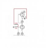
That schematic looks right to me. While you are at it I would also bypass the bottom cathode resistor with 220uF. You could also increase R14 to 470K.
Cheers
Ian
The new circuit may be more noisy than the original one, because of the 47k input resistor, but this might not matter in a line stage where signal levels are presumably quite high. It will have lower output impedance (good) but no better driving ability.
The new circuit may be more noisy than the original one, because of the 47k input resistor, but this might not matter in a line stage where signal levels are presumably quite high. It will have lower output impedance (good) but no better driving ability.
A 47K resistor in a 20KHz bandwidth produces a thermal noise of just under 4uV which will appear at the output as 8uV which is -102dBV. The noise generated by the tube is likely to be 10 times this value.
I am not sure about the comment on driving capability being 'no better'. It's peak current capability is unchanged so I agree with the statement to that extent. However, since the output impedance is lower the HF droop driving capacative cables is better and the distortion spectra driving any given load to any level below clipping will be better too. Of all the available all tube preamp topologies, the SRPP already has the 'best' driving capability as it is the only truly push pull circuit so it's pretty hard to make it better. Not to mention the fact it is only being asked to drive a power amp which is hardly a demanding load.
Cheers
Ian
Excellent, thanks 🙂ok, I will give it a try
but please, have someone else to approve it
Thanks Ian, very much appreciated 🙂That schematic looks right to me. While you are at it I would also bypass the bottom cathode resistor with 220uF. You could also increase R14 to 470K.
Cheers
Ian
Couple of questions :
Is R14 the bottom cathode resistor?
What wattage resistors should I get for the NFB? I guess 0.25w would be fine?
I understand NFB a bit more now after reading this basic guide Negative Feedback
I like how the inverse circuit / tube noise is also fed back and cancelled out. Sounds neat and simple and effective.
Cheers,
James
No no , don't change R14 ( the bottom cathode resistor ) , you can change the input resistor 240K make it 470K , this will reduce the gain further , I believe that ruffrecords wanted to say that .
Excellent, thanks 🙂
Thanks Ian, very much appreciated 🙂
Couple of questions :
Is R14 the bottom cathode resistor?
What wattage resistors should I get for the NFB? I guess 0.25w would be fine?
Correct, it is R14 on the schematic you recently posted. You don't need to change it but you should bypass it with 220uF. 0.25 watt resisotrs will be fine for the NFB components.
I understand NFB a bit more now after reading this basic guide Negative Feedback
I like how the inverse circuit / tube noise is also fed back and cancelled out. Sounds neat and simple and effective.
Cheers,
James
If you want a bit more detail on the theory behind NFB there is this article I wrote a few years back:
http://www.ianbell.ukfsn.org/nfb101/nfb101.pdf
Cheers
Ian
That's a little alarmist! This preamp has DC heaters, so if hum is not a problem then the equivalent input noise voltage of an ECC82 is more like 1uV in the audio band. Not a bit deal in this case.A 47K resistor in a 20KHz bandwidth produces a thermal noise of just under 4uV which will appear at the output as 8uV which is -102dBV. The noise generated by the tube is likely to be 10 times this value.
That's a little alarmist! This preamp has DC heaters, so if hum is not a problem then the equivalent input noise voltage of an ECC82 is more like 1uV in the audio band. Not a bit deal in this case.
2.5/gm might lead you to believe so but if you make measurements with real world tubes you find it is not the case. I have measured the noise of hundreds of tubes and rarely does one creep below 2uV EIN.
Cheers
Ian
Why bypass it with 220uF ? since the The Whole Story is about reducing the gain of the preamp .Correct, it is R14 on the schematic you recently posted. You don't need to change it but you should bypass it with 220uF. 0.25 watt resisotrs will be fine for the NFB components.
Cheers
Ian
Why bypass it with 220uF ? since the The Whole Story is about reducing the gain of the preamp .
NFB is more effective with the highest open loop gain. Also, not decoupling the cathode resistor increases the effective ra of the tube by at least mu*Rk. Since distortion in an SRPP is caused by the relatively high ra of the bottom tube being loaded by the relatively low impedance of the top tube, if you increase the bottom tube ra you only increase the distortion. Since this also decreases the open loop gain which also increases distortion, I recommend bypassing the cathode resistor.
Cheers
Ian
thanks again Ian,
what kind of voltages should I expect to see across the cathode resistor?
I'll get some bits ordered up, but I won't have an opportunity to get the meter on the real circuit for a day or 2 and wanted to be sure that the bypass cap I get is of a sufficient voltage rating.
regards,
James
what kind of voltages should I expect to see across the cathode resistor?
I'll get some bits ordered up, but I won't have an opportunity to get the meter on the real circuit for a day or 2 and wanted to be sure that the bypass cap I get is of a sufficient voltage rating.
regards,
James
thanks again Ian,
what kind of voltages should I expect to see across the cathode resistor?
I'll get some bits ordered up, but I won't have an opportunity to get the meter on the real circuit for a day or 2 and wanted to be sure that the bypass cap I get is of a sufficient voltage rating.
regards,
James
There will only be a few volts at most across the cathode resistor. I usually use a 16V or 25V rated part.
Cheers
Ian
Remember that the increase in ra will be largely linear so provided the valve has fairly constant mu it will not add to distortion. Higher ra coming from the valve itself adds to distortion because that is non-linear, but degeneration is different.ruffrecords said:if you increase the bottom tube ra you only increase the distortion.
Yes , the cap will delete the degeneration feedback and will increase the gain , stages with high gain leads to higher distortion , plus the non linearities of an electrolytic capacitor .
One positive thing with the cap here is the increased driving capability of the stage .
One positive thing with the cap here is the increased driving capability of the stage .
perfect, thanks 🙂There will only be a few volts at most across the cathode resistor. I usually use a 16V or 25V rated part.
Cheers
Ian
I would question your results- I've not found a single ECC82 to exceed 2uV, unless it had interface resistance (2.5/gm would predict about 0.7uV). Ten times 4uV is certainly unrealistic. But I guess this is kinda moot for this thread!🙄2.5/gm might lead you to believe so but if you make measurements with real world tubes you find it is not the case. I have measured the noise of hundreds of tubes and rarely does one creep below 2uV EIN.
stages with high gain leads to higher distortion
As a general statement this is demonstrably not true.
, plus the non linearities of an electrolytic capacitor .
which will be orders of magnitude below the base level distortion of the SRPP.
Cheers
Ian
I would question your results- I've not found a single ECC82 to exceed 2uV, unless it had interface resistance (2.5/gm would predict about 0.7uV). Ten times 4uV is certainly unrealistic. But I guess this is kinda moot for this thread!🙄
Then I have to ask how you made the measurement? 40uV at the output of a tube working open loop with a gain of x20 would be very good in my experience. Perhaps we should take this to a separate thread. I am always fascinated by other peoples' noise measurements.
Cheers
Ian
- Status
- Not open for further replies.
- Home
- Amplifiers
- Tubes / Valves
- Reducing gain in a SRPP circuit with ECC82?