Posts # 3552,3554,3558
Hi David,
Thanks again for you effort it is very much appreciated.
Looking at Bagby's software (Woofer Box Model and Circuit Designer, Version 4.5 12/4/2009) again, it looks like I may have found the basic error: when switching the "Selectable Textbook High Pass Filter" from "Fourth Order Butterworth" to "Fourth Order Linkwitz-Riley" there is no change in the "Circuit Shape" as indicated on the graph; but, when using both of the "Optional Second Order Adjustable High Pass Filter Stages" @ Fc=24Hz Q=0.707 [Gain(dB)=-3.0dB] I get the expected 4th order LR response on the graph. The LP section also shows the same curve for Bw and LR. In other words, I think I may have found a bug (or two) in Bagby's spreadsheet, not in Hornresp.
I'll attach a few screenprints:
1. Bagby's Input screen
2. BP: Dual 2nd order Butterworth HP plus 4th order LR LP
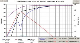
3. BP: 4th order LR (both: HP and LP)
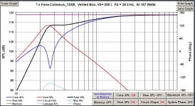
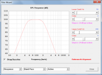
4. HP: 4th Bw
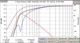
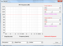
5. HP: 4th LR
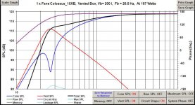
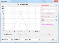
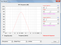
6. HP: 2x 2nd Bw
7. SPL w/o filters
8. I'll tried to add Bagby's Excel file by changing the extension from .xlsm to .txt; but, the file size is too big (I can email it to anyone interested).
So, at this time it looks to me like all is well in Hornresp land.
Regards,
P.S.: Just downloaded and tested Baby's Version 5.0, same result as Version 4.5.
Hi David,
Thanks again for you effort it is very much appreciated.
Looking at Bagby's software (Woofer Box Model and Circuit Designer, Version 4.5 12/4/2009) again, it looks like I may have found the basic error: when switching the "Selectable Textbook High Pass Filter" from "Fourth Order Butterworth" to "Fourth Order Linkwitz-Riley" there is no change in the "Circuit Shape" as indicated on the graph; but, when using both of the "Optional Second Order Adjustable High Pass Filter Stages" @ Fc=24Hz Q=0.707 [Gain(dB)=-3.0dB] I get the expected 4th order LR response on the graph. The LP section also shows the same curve for Bw and LR. In other words, I think I may have found a bug (or two) in Bagby's spreadsheet, not in Hornresp.
I'll attach a few screenprints:
1. Bagby's Input screen
2. BP: Dual 2nd order Butterworth HP plus 4th order LR LP
3. BP: 4th order LR (both: HP and LP)
4. HP: 4th Bw
5. HP: 4th LR
6. HP: 2x 2nd Bw
7. SPL w/o filters
8. I'll tried to add Bagby's Excel file by changing the extension from .xlsm to .txt; but, the file size is too big (I can email it to anyone interested).
So, at this time it looks to me like all is well in Hornresp land.
Regards,
P.S.: Just downloaded and tested Baby's Version 5.0, same result as Version 4.5.
Attachments
-
 WBCD_Input.jpg30.6 KB · Views: 193
 -
 WBCD_Flat.jpg64.6 KB · Views: 96
 -
 WBCD_HP_2x_24Hz_2nd_Bw.jpg63.5 KB · Views: 103
 -
 WBCD_HP_24Hz_4th_LR.jpg62.8 KB · Views: 180
 -
 WBCD_HP_24Hz_4th_Bw.jpg61.5 KB · Views: 188
 -
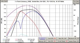 WBCD_BP_24Hz_82Hz_4th_LR.jpg64.7 KB · Views: 185
 -
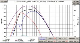 WBCD_BP_24Hz_HP_2x_2nd_BW_82Hz_LP_4th_LR.jpg65.1 KB · Views: 183
Last edited:
Hi kees52,
Post #3560: "...I think you have to experiment in real live to get it right."
I'm a great believer in experimenting; but, if we cannot simulate the electrical behaviour of a relatively "simple" filter circuit with some accuracy anymore, then we would have taken a vast step backwards. So, we may experiment for whole system response and integration; but we should be able to get the basic (particularly electronic) building block simulations correct.
Regards,
Hi kees52,
Post #3560: "...I think you have to experiment in real live to get it right."
I'm a great believer in experimenting; but, if we cannot simulate the electrical behaviour of a relatively "simple" filter circuit with some accuracy anymore, then we would have taken a vast step backwards. So, we may experiment for whole system response and integration; but we should be able to get the basic (particularly electronic) building block simulations correct.
Regards,
Hi TB
Afcourse you are right about that, simulating has bring a lot of deeper science to us in DIY, thanks to David and other programmers.
I did mean when the simulation is a like, then fine tune, you will see that loudspeakers are a big challence for filters, I do like to use impedance correction circuits, it make better behavior and audio is more relaxed, the same as you use a very good speaker who is very smood frequentieplot.
I did make amps without sims long ago, it did costs a lot more because of blown parts, now it is very rare that i do blow something thanks toy simulations.
regards
kees
I don't understand what you mean withand similarly for the others.
Hi Andrew,
"Red trace - 4th-order Butterworth, 2 x -3dB = -6dB at fc (94dB - 100dB)" shows the combined effect of the two filter gain responses given in Attachment 1 below, when applied to a constant 100dB signal. At the cutover frequency of 100 Hz the gain is -3dB each for the high-pass and low-pass filters. When used together to form a band-pass filter, but with both the HF and LF cutoff frequencies at 100 Hz, the gain at the single common 100 Hz cutover frequency becomes (-3db) + (-3db) = -6dB, as shown in my earlier post.
Similarly, "Grey trace - 4th-order Linkwitz-Riley, 2 x -6dB = -12dB at fc (88dB - 100dB)" shows the combined effect of the two filter gain responses given in Attachment 2 below, when applied to a constant 100dB signal. At the cutover frequency of 100 Hz the gain is -6dB each for the high-pass and low-pass filters. When used together to form a band-pass filter, but with both the HF and LF cutoff frequencies at 100 Hz, the gain at the single common 100 Hz cutover frequency becomes (-6db) + (-6dB) = -12dB, as shown in my earlier post.
The other results shown in my earlier post were generated in a similar fashion.
As mentioned previously, it is important to remember that two separate filter gains are being applied to a single signal - as distinct from two separate signals being combined.
If you can see any flaws in my reasoning, please let me know.
Kind regards,
David
Attachments

So, at this time it looks to me like all is well in Hornresp land.
Excellent 🙂.
Many thanks Oliver, for taking the time to investigate the matter further, and for letting me know the outcome.
Kind regards,
David
We have the TH1 option that jumps the back side of the driver from S4 to S3 leaving us with a second segment after the driver.
How about TH2 jumping the frontside of the driver from S2 to S1 giving us another segment between the drivers. A chamber could be used if the simulation needed the cushion that L12 provided before. I have seen many simulations with L12 already at the shortest length possible so why not.
How about TH2 jumping the frontside of the driver from S2 to S1 giving us another segment between the drivers. A chamber could be used if the simulation needed the cushion that L12 provided before. I have seen many simulations with L12 already at the shortest length possible so why not.
How about TH2 jumping the frontside of the driver from S2 to S1 giving us another segment between the drivers.
Hi David_Web,
This option was recently requested by Djim in Post #3530.
The code changes necessary to implement the functionality would be significant - particularly the modifications to the Loudspeaker Wizard. Unfortunately from my perspective the work required far outweighs the relatively small additional design flexibility to be gained.
Sorry, but you will have to use AkAbak if you wish to simulate such a configuration.
Kind regards,
David
I still don't follow.
Can some one else step in and explain that to me?
Hi Andrew,
I will try one more time, before admitting defeat and then letting someone else have a go 🙂.
"Red trace - 4th-order Butterworth, 2 x -3dB = -6dB at fc (94dB - 100dB)"
Imagine a 4th-order Butterworth band-pass filter being applied to a 100dB signal:
Attachment 1 below shows the un-filtered 100dB signal.
Attachment 2 shows the filtered signal when lower fc = 25 Hz and upper fc = 400 Hz.
Attachment 3 shows the filtered signal when lower fc = 50 Hz and upper fc = 200 Hz.
Attachment 4 shows the filtered signal when lower fc = 100 Hz and upper fc = 100 Hz.
Attachment 4 is the same as the red trace referred to above.
Kind regards,
David
Attachments

Ah, I get what you have been trying to describe.
A bandpass filter that has NO passband !
Why ?
A bandpass filter that has NO passband !
Why ?
Hi David,
Thanks again for you effort it is very much appreciated.
Looking at Bagby's software (Woofer Box Model and Circuit Designer, Version 4.5 12/4/2009) again, it looks like I may have found the basic error: when switching the "Selectable Textbook High Pass Filter" from "Fourth Order Butterworth" to "Fourth Order Linkwitz-Riley" there is no change in the "Circuit Shape" as indicated on the graph; but, when using both of the "Optional Second Order Adjustable High Pass Filter Stages" @ Fc=24Hz Q=0.707 [Gain(dB)=-3.0dB] I get the expected 4th order LR response on the graph. The LP section also shows the same curve for Bw and LR. In other words, I think I may have found a bug (or two) in Bagby's spreadsheet, not in Hornresp.
I'll attach a few screenprints:
1. Bagby's Input screen
2. BP: Dual 2nd order Butterworth HP plus 4th order LR LP
3. BP: 4th order LR (both: HP and LP)
4. HP: 4th Bw
5. HP: 4th LR
6. HP: 2x 2nd Bw
7. SPL w/o filters
8. I'll tried to add Bagby's Excel file by changing the extension from .xlsm to .txt; but, the file size is too big (I can email it to anyone interested).
So, at this time it looks to me like all is well in Hornresp land.
Regards,
P.S.: Just downloaded and tested Baby's Version 5.0, same result as Version 4.5.
I suspect you are not clicking the "Load Low Pass" button and only scrolling to the crossover type of your choosing. If you don't click that command button it will not load the crossover transfer function coefficients you have selected and you will simply have whatever transfer function was previously loaded. Try that and let me know if that's all it was. I know I can see the difference between LR and BW when I do this.
Jeff B.
Hi Andrew,
I had a feeling that we would get there eventually 🙂.
As indicated in my initial post, the whole exercise was a sanity check only - it was not intended to have any practical application. In the light of Oliver's earlier comments I simply wanted to make sure that the high-pass and low-pass filters were combining correctly when used together as a band-pass filter. One easy test was to confirm that the overall response at a common 100 Hz cutoff frequency was -6dB for a Butterworth BPF (-3dB due to the HPF and -3dB due to the LPF), and -12dB for a Linkwitz-Riley BPF (-6dB due to the HPF and -6dB due to the LPF). The results did indeed show this.
Kind regards,
David
Ah, I get what you have been trying to describe.
I had a feeling that we would get there eventually 🙂.
A bandpass filter that has NO passband !
Why ?
As indicated in my initial post, the whole exercise was a sanity check only - it was not intended to have any practical application. In the light of Oliver's earlier comments I simply wanted to make sure that the high-pass and low-pass filters were combining correctly when used together as a band-pass filter. One easy test was to confirm that the overall response at a common 100 Hz cutoff frequency was -6dB for a Butterworth BPF (-3dB due to the HPF and -3dB due to the LPF), and -12dB for a Linkwitz-Riley BPF (-6dB due to the HPF and -6dB due to the LPF). The results did indeed show this.
Kind regards,
David
I suspect you are not clicking the "Load Low Pass" button and only scrolling to the crossover type of your choosing. If you don't click that command button it will not load the crossover transfer function coefficients you have selected and you will simply have whatever transfer function was previously loaded. Try that and let me know if that's all it was. I know I can see the difference between LR and BW when I do this.
Jeff B.
Hi Jeff,
In the light of Oliver's comments in Post #3552, I would be very interested to know if you see any problems in the active filter response results produced by Hornresp. Thanks.
Kind regards,
David
Hi Jeff B,
Post #3571: "... suspect you are not clicking the "Load Low Pass" button and only scrolling to the crossover type of your choosing. If you don't click that command button it will not load the crossover transfer function coefficients you have selected and you will simply have whatever transfer function was previously loaded..."
You are indeed correct, somehow I totally overlooked the "Load ... Pass" buttons. I found the ON/OFF buttons, and the DISABLED/ENABLED button, but not the LOAD buttons.
While I have your attention, sometimes the spreadsheet seems to hang with all graphs devoid of data lines, and sometimes it does not want to recalculate; only leaving the program, and reopening helps. Just more operator problems, or "normal" Microsoft behaviour? I'm running a Windows XP SP3 laptop.
Generally, I really like your simulator, and it's results seem to track closely with Hornresp (given a competent operator). 🙂 Thank you so very much for looking into this.
Regards,
Last edited:
Post #3573
Hi David,
While your question is directed at Jeff B, I just want to add that after properly using Jeff's software the resultant curves now look a lot like the ones generated in Hornresp.
Thanks again for your efforts.
Regards,
Hi David,
While your question is directed at Jeff B, I just want to add that after properly using Jeff's software the resultant curves now look a lot like the ones generated in Hornresp.
Thanks again for your efforts.
Regards,
Hi Jeff,
In the light of Oliver's comments in Post #3552, I would be very interested to know if you see any problems in the active filter response results produced by Hornresp. Thanks.
Kind regards,
David
Judging by the screenshots shown on the last few pages, they all appear correct to me. Are you using a polynomial and just changing coefficients for different crossover orders and shapes? That what mine does. I use the same equation whether it's a 1st order Butterworth or an 8th order LR. I just use a table that drops the coefficients in based on the selection and it creates the transfer function shape.
Jeff
Hi Jeff B,
Post #3571: "... suspect you are not clicking the "Load Low Pass" button and only scrolling to the crossover type of your choosing. If you don't click that command button it will not load the crossover transfer function coefficients you have selected and you will simply have whatever transfer function was previously loaded..."
You are indeed correct, somehow I totally overlooked the "Load ... Pass" buttons. I found the ON/OFF buttons, and the DISABLED/ENABLED button, but not the LOAD buttons.
While I have your attention, sometimes the spreadsheet seems to hang with all graphs devoid of data lines, and sometimes it does not want to recalculate; only leaving the program, and reopening helps. Just more operator problems, or "normal" Microsoft behaviour? I'm running a Windows XP SP3 laptop.
Generally, I really like your simulator, and it's results seem to track closely with Hornresp (given a competent operator). 🙂 Thank you so very much for looking into this.
Regards,
I have not ran across anything odd with this program on different computers and it seems to work great on my old XP machine with Office 2000. My Passive Crossover Designer can get a little funky sometimes in Office 2010, and none of my stuff works with a 64 bit Office application. You can thank Microsoft for that, they changed how the VBA works for the 64 bit and it won't compile my VBA modules correctly and shoots back a bunch of errors. I am not going to rewrite things at this point, so I guess that's life.
Post #3577
Hi Jeff B,
I experimented some more today, and the main "hang up" seems to occur immediately after saving. The curves disappear from the graphs, and won't come back. The different F9 recalculation key combinations won't bring it back, and the easy work-around is to close, and re-open the program. Not a big problem, as the last information seems to be saved.
I can fully understand, that you don't want to "rewrite things". I wouldn't either. Thanks again for a very useful program.
Regards,
While your question is directed at Jeff B, I just want to add that after properly using Jeff's software the resultant curves now look a lot like the ones generated in Hornresp.
Hi Oliver,
Excellent, many thanks for confirming this.
Kind regards,
David
Judging by the screenshots shown on the last few pages, they all appear correct to me. Are you using a polynomial and just changing coefficients for different crossover orders and shapes?
Hi Jeff,
Thanks for confirming that the Hornresp results look okay.
I use the following expressions to calculate the normalised gain G at frequency f where fc = filter cutoff frequency and n = filter order.
Low-pass Butterworth:
G = 1 / Sqrt(1 + (f / fc) ^ (2 * n))
High-pass Butterworth:
G = 1 / Sqrt(1 + (fc / f) ^ (2 * n))
Low-pass Linkwitz-Riley:
G = 1 / (1 + (f / fc) ^ n)
High-pass Linkwitz-Riley:
G = 1 / (1 + (fc / f) ^ n)
I calculate band-pass gain simply by multiplying the appropriate high-pass and low-pass gains together.
Kind regards,
David
- Home
- Loudspeakers
- Subwoofers
- Hornresp