Hello guys!
Yesterday I decide to use 180pF mica looks really good 😀 I'm going to order the transistors I need and some resistors that I don't have also the insulator for the TO-3 I don't have those, so yes I need them, the board on this pictures look a bit large than what it is but is ok on the second one I might just leave in that size it does not bother me at all well here are the last images then I have to wait for the part the get here in Puerto Rico good day guys 😀
Regards
Vargas
Nice work, what about PSU and protect?
Regards
Nice work, what about PSU and protect?
Regards
I will make a layout for a power supply and later I will make the speaker protection 🙂 I can't wait to make the other channel but need that good thinking mister Mile , I might forget that.
Regards
Juan
Very nice PCB, thank you Willy.
Can you pls share HX-11 Ver. 3.3. PCB in PDF?
Regards
Thanks... here it is.
Regards,
Attachments
Apex NE555 Protection
Hi mister Mile, I read all pages of this thread and I decide to do the AX20 my own pcb design with NE555 protection inside, because I have some experience. I done, but I started test the protection alone first, the problem is when I conect 12VAC, few seconds ago the rele goes on and off and never stop this process until I put some hot in NTC (rele goes on), but when the NTC become cold the on / off process start again. I check and recheck the components and pcb design and I did not found errors. Can you help me ? With your good ideas 🙂
Pozdrav in advance
Just an off the cuff comment in the hope its appropriate...
The NE555 must have a 100uf cap directly across pins 1 and 8 to absorb the huge current spike the device draws when changing state. Without and the device can just keep resetting itself. Also make sure pin 5 ? is correctly decoupled.
The NE555 must have a 100uf cap directly across pins 1 and 8 to absorb the huge current spike the device draws when changing state. Without and the device can just keep resetting itself. Also make sure pin 5 ? is correctly decoupled.
Thanks very much Mooly, I am not a electronic engineer, sorry, so here de questions. Cap 100uf is there, is ok, I Think 🙂 but I changed the value of decouple capacitor 15n to 470n, did I something wrong ? with this value DC protect work, delay work but if I hot NTC nothing happens.
Thanks Mooly
Thanks Mooly
So you have the 100uf cap and pin 5 is decoupled by either a 15 or 470nf. I would have to see the circuit and how this this NTC is wired and what it does 🙂
(if you mean the NTC is a soft start then the problems could be that the NE555 supply is rising to slowly... but that's just a guess... I haven't followed the thread closely enough so would have to see the exact circuit you have used)
(if you mean the NTC is a soft start then the problems could be that the NE555 supply is rising to slowly... but that's just a guess... I haven't followed the thread closely enough so would have to see the exact circuit you have used)
Hi mister Mile, I read all pages of this thread and I decide to do the AX20 my own pcb design with NE555 protection inside, because I have some experience. I done, but I started test the protection alone first, the problem is when I conect 12VAC, few seconds ago the rele goes on and off and never stop this process until I put some hot in NTC (rele goes on), but when the NTC become cold the on / off process start again. I check and recheck the components and pcb design and I did not found errors. Can you help me ? With your good ideas 🙂
Pozdrav in advance
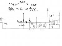
NE555 triger if voltage is from 1/3Vcc nad 2/3Vcc, you must add resistors in series and parallel conection with NTC to keep voltage over 1/3Vcc and under 2/3Vcc whan NTC cold, if NTC hot voltage must drop under 1/3Vcc to triger NE555.
Regards
Hi mister Mile, thanks for your quick reply, but where can I get the Vcc as you say ? Should I get between NTC terminals ?
Regards
Regards
Hi mister Mile, thanks for your quick reply, but where can I get the Vcc as you say ? Should I get between NTC terminals ?
Regards
Voltage on pins 2,6 of NE555
Hi mister Mile, again 🙂 I put a trim instead 100R and the other trim in parallel with NTC. NTC cold I have 5,3Vcc between pins 2,6 to ground and rele ON, NTC hot 5,5Vcc (nothing happens). It should be under 1/3Vcc am I wrong ?
Regards
Regards
Hi mister Mile, again 🙂 I put a trim instead 100R and the other trim in parallel with NTC. NTC cold I have 5,3Vcc between pins 2,6 to ground and rele ON, NTC hot 5,5Vcc (nothing happens). It should be under 1/3Vcc am I wrong ?
Regards
NTC must have 10k cold and about 1k hot. If NTC is 1k voltage on pins 2,6 increase over 2/3 Vcc and NE555 disconnect relay.
Attachments
sr200
Hi Mr Apex
I have a question .
Can i use Bf493 instead of 2N5401 TO sr 200 studio ref?
Thanks.
Hi Mr Apex
I have a question .
Can i use Bf493 instead of 2N5401 TO sr 200 studio ref?
Thanks.
Last edited:
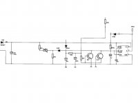
P { margin-bottom: 0.21cm; direction: ltr; color: rgb(0, 0, 0); }P.western { font-family: "Times New Roman",serif; font-size: 12pt; }P.cjk { font-family: "WenQuanYi Micro Hei"; font-size: 12pt; }P.ctl { font-family: "Lohit Hindi"; font-size: 12pt; }A:visited { }A:link { } [FONT=Times New Roman, serif]Dear mister Mile, I’m a little bit puzzled about this circuit, since you say I need to use an NTC to sense the temperature.[/FONT]
[FONT=Times New Roman, serif]Starting from de DC protection, Q23 and Q24 will impose approximately 0V when DC appears at Amplifier output.[/FONT]
[FONT=Times New Roman, serif]While in DC fault, trigger will happen when Pin2 (=Pin6) goes lower than 1/3Vcc because Pin2 will SET the output to Vcc, deenergizing relay coil. No doubt about.[/FONT]
[FONT=Times New Roman, serif]Starting condition: C52 will wake up discharged, therefore Pin2 (=Pin6) will SET output to Vcc disabling relay, and will charge through R116 till Pin6 (=Pin2) will reach 2/3Vcc. At this point, Pin6 will RESET the output to 0V energizing relay coil. No doubt once more.[/FONT]
[FONT=Times New Roman, serif]In that case, it seems to me that when we need that 555 output should be SETED to VCC in order to deenergize relay coil, we need that Pin2 (=Pin6) should be forced to go lower than 1/3Vcc, and the only way to accomplish that, concerning thermal protection, is to increase voltage through thermistor while temperature should also increase, therefore a PTC should be needed. Am I right? Or completely confused?[/FONT]
[FONT=Times New Roman, serif]Pozdrav[/FONT]
Hi Mr Apex
I have a question .
Can i use Bf493 instead of 2N5401 TO sr 200 studio ref?
Thanks.
Please post in SR200 thread. MPSA92 can be use instead 2N5401.
Regards
Apex,
what is the effect of adding the NTC/PTC into the triggering route to the 555?
For thermal protect Vref must be over 2/3Vcc on cold amp and under 1/3Vcc on 90deg. This can be done useing NTC or PTC resistors in circuit.
Attachments
- Home
- Amplifiers
- Solid State
- 100W Ultimate Fidelity Amplifier