Hi!
I'm planning to build a sub for my living room, to go with the floorstanders I'm currently building (Seas CA18RNX/27TDC). The sub will have to go under the sofa due to lack of space elsewhere, as well as WAF...
So... I have a space of roughly 52 x 29 x 7,5 inches available. Originally I wanted to build Bjorn Johannesens Hideaway TL sub, as I found the design both interesting and clever, but I realized that the shape of my sofa unfortunately doesn't allow for that design.
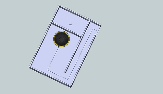
Then I thought why not try to design a TL myself. So, inspired by Bjorn Johannesens Hideaway, I got Martin J Kings worksheets and tested a design based on the same driver, the 10 inch Peerless 830668. Basically what I have tried to do is place the driver facing up, on top of a fairly flat (6 inches) box and see if I could get a satisfactory result from the simulations.
This is my first go at a TL sub, so I'm sure there are lots of room for improvement, and I'd love to hear some opinions on this "first draft". 😀
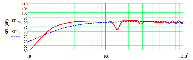
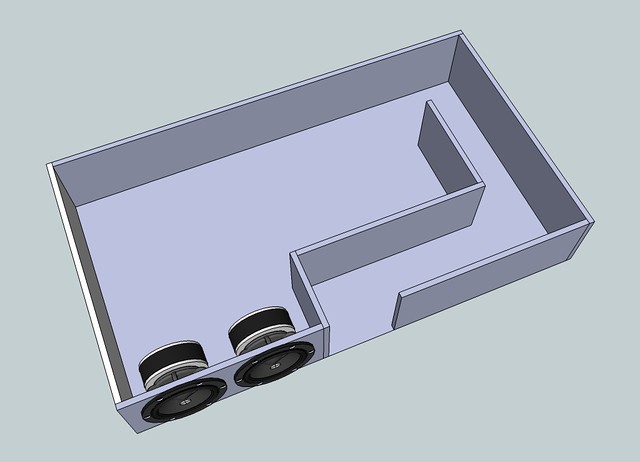
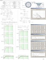
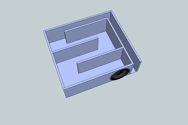
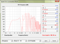
I don't know if I can put the whole simulation up here (PDF), but I'll start with the SPL response, a quick sketchup of the box, and a couple of questions. 🙂
Then the first set of questions:
To me the response doesn't look half bad, any thoughts?
Should I be worried that the first part of the line is only 6 inches tall but almost 22 inches wide?
There is a 1,4 inch clearance between the bottom of the enclosure and the back of the driver. Too little?
Any fundamental design flaws that I don't see....? 😕
Any thoughts are appreciated! Thanks! 😀
I'm planning to build a sub for my living room, to go with the floorstanders I'm currently building (Seas CA18RNX/27TDC). The sub will have to go under the sofa due to lack of space elsewhere, as well as WAF...
So... I have a space of roughly 52 x 29 x 7,5 inches available. Originally I wanted to build Bjorn Johannesens Hideaway TL sub, as I found the design both interesting and clever, but I realized that the shape of my sofa unfortunately doesn't allow for that design.
Then I thought why not try to design a TL myself. So, inspired by Bjorn Johannesens Hideaway, I got Martin J Kings worksheets and tested a design based on the same driver, the 10 inch Peerless 830668. Basically what I have tried to do is place the driver facing up, on top of a fairly flat (6 inches) box and see if I could get a satisfactory result from the simulations.
This is my first go at a TL sub, so I'm sure there are lots of room for improvement, and I'd love to hear some opinions on this "first draft". 😀
I don't know if I can put the whole simulation up here (PDF), but I'll start with the SPL response, a quick sketchup of the box, and a couple of questions. 🙂
Then the first set of questions:
To me the response doesn't look half bad, any thoughts?
Should I be worried that the first part of the line is only 6 inches tall but almost 22 inches wide?
There is a 1,4 inch clearance between the bottom of the enclosure and the back of the driver. Too little?
Any fundamental design flaws that I don't see....? 😕
Any thoughts are appreciated! Thanks! 😀
When I saw this I immediately thought of this driver: Tymphany LAT 500, there is a bigger 700 version also but I think that one would be too big to fit under the sofa unless the 7,5 inch measurement is internal height of the box.
The LATs s if I understand correctly not that cost efficient when compared to a normal bigger sub driver but it could give you a very short box. If I remember correctly the drivers are push-push so it cancels vibration which should be nice in your case also since dual drivers of ~ 10 inch+ in a PP set up would be impossible to fit.
EDIT: It seems that the driver is no longer available, so might not be an option at all.
Last edited:
Tang band seems to have shallow oval subwoofer drivers though, like this one: http://www.tb-speaker.com/detail/1208_03/w69-1042j.htm
It's much cheaper than the LAT also so you could stack 2 for PP vibration cancellation and distortion reduction. If you need higher SPL you could even get 4.
It's much cheaper than the LAT also so you could stack 2 for PP vibration cancellation and distortion reduction. If you need higher SPL you could even get 4.
Tang band seems to have shallow oval subwoofer drivers though, like this one: http://www.tb-speaker.com/detail/1208_03/w69-1042j.htm
It's much cheaper than the LAT also so you could stack 2 for PP vibration cancellation and distortion reduction. If you need higher SPL you could even get 4.
Hmm, I'm a bit confused about push/push, how would I mount the drivers in the box? Is it worth going down this route if the current driver works (in terms of physical size)? And how would it affect the line?
Hmm, I'm a bit confused about push/push, how would I mount the drivers in the box? Is it worth going down this route if the current driver works (in terms of physical size)? And how would it affect the line?
You mount them inside the box like this: http://www.linkwitzlab.com/images/graphics/d_woof1.gif
But instead of an open baffled dipole you use it in a transmission line. For a sub it is very worth it, mechanical vibration is reduced to almost nothing and second order distortion is massively reduced also. Such enclosures are discussed here also: http://www.diyaudio.com/forums/subwoofers/177905-thread-those-interested-ppsl-enclosures.html
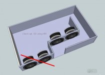
If I see correctly the output would be upwards so you could do it like this:
Attachments
Last edited:
😀...I don't know if I can put the whole simulation up here (PDF), but I'll start with the SPL response, a quick sketchup of the box, and a couple of questions. 🙂
Hi linaudio,
A pdf would be nice to look at.
To me the response doesn't look half bad, any thoughts?
I don't think your picture is reflected by the posted FR graph.
There is a 1,4 inch clearance between the bottom of the enclosure and the back of the driver. Too little?
That clearance shoud be adequate.
b🙂
Attachments
Thanks OllBoll, I'll have a read through that thread, concept looks interesting. I checked out the TB driver, and total SD of two of them exceeds that of a single 10", so it wouldn't be a "downgrade" in that respect. 🙂
Hi linaudio,
A pdf would be nice to look at.
Hi Bjorn, and thanks for the comments. 🙂
I've redone the simulation (a few mistakes in the first one) and made the PDF available here:
https://dl.dropboxusercontent.com/u/71486104/TL_sofasub.pdf
How does it look?
Thanks,
Oyvind
Last edited:
I don't think your picture is reflected by the posted FR graph.
Bjorn, I think I misread this the first time. I assume you mean that since the sub is to be placed under a sofa, the far field FR graph will not be an accurate representation of real life? Is there a way to compensate for this in the simulation?
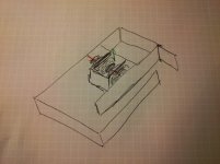
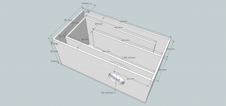
If the placement of the driver is not ideal, I could possibly squeeze a couple of extra inches in and get enough height to place 2x 8" drivers next to the opening on the short end of the box. Would this be a better starting point in terms of driver and opening placement than my first attempt? As long as I can make the line work with this layout obviously... (The line in the attached picture is only a quick sketch, not yet simulated)
Bjorn, I think I misread this the first time. I assume you mean that since the sub is to be placed under a sofa, the far field FR graph will not be an accurate representation of real life? Is there a way to compensate for this in the simulation?
If the placement of the driver is not ideal, I could possibly squeeze a couple of extra inches in and get enough height to place 2x 8" drivers next to the opening on the short end of the box. Would this be a better starting point in terms of driver and opening placement than my first attempt? As long as I can make the line work with this layout obviously... (The line in the attached picture is only a quick sketch, not yet simulated)
Hi Öyvind,
Thank you for posting the .pdf..IMO,You've done a very good simulation
..the far field FR graph will not be an accurate representation of real life?
Yes,The main problem for a believable simulated FR depends on an accurate system model of your room and the sofa-sub placement.
..Would this be a better starting point..
IMO:Yes.
Have a look at an suggestion based on your first simulation attempt:
b🙂
Attachments
Long time no sub... I´ve been too busy at work to get any further with this, but I´ve finally got some time to play. 🙂
Bjorno, sorry for the late reply. Thanks a lot for you reply and suggestion, much appreciated! Unfortunately, I don´t have enough space for the alternative driver placement (I would have to raise the entire sofa a few inches, and I´m not sure that would be appreciated by the rest of the family.. 😛 )
I´m actually considering going down an alternative route with this. I´ve simulated a single TangBand W6-1139SIF in a smaller box, for several reasons:
1. I can build a second one and fit both under the sofa if I feel one isn´t enough.
2. The format means I can use it in other settings as well, for example under the desk in my office.
3. If a build a second one, I can experiment with placing the two subs different places in the room.
So... Here is the new design, and link to the sim. Looks fairly good to me, but if anyone can spot something I havent´t seen, then please let me know! 😀
https://www.dropbox.com/s/2bc9xnliw6f51gq/Sofasub_W6_sim.pdf
Bjorno: I´ve never used hornresp, but I´m very curious to learn how to sim a T-TQWT like you suggested. I assume this would be done using MJK worksheets and hornresp in combination? Do you know anywhere online I can read more about it?
RE: T-TQWT info
bjorno posted a .pdf on the forum, somewhere, called
Pearls from Martin J. King Quarter Wave Design.
An introduction by Bjorn Johannesen, Denmark. September the 1st 2005.
It is an excellent resource however I can not find it again on the forum.
.
I have a pdf of it but do not know how to post it or even if that would be appropriate as I did not write it.
If you can find it it will tell you allot.
Dave
SNIP...
Bjorno: I´ve never used hornresp, but I´m very curious to learn how to sim a T-TQWT like you suggested. I assume this would be done using MJK worksheets and hornresp in combination? Do you know anywhere online I can read more about it?
bjorno posted a .pdf on the forum, somewhere, called
Pearls from Martin J. King Quarter Wave Design.
An introduction by Bjorn Johannesen, Denmark. September the 1st 2005.
It is an excellent resource however I can not find it again on the forum.
.
I have a pdf of it but do not know how to post it or even if that would be appropriate as I did not write it.
If you can find it it will tell you allot.
Dave
This one? Not a pdf though, so don't know if there's any revisions: Pearls from Martin J King Quarter Wave Design
GM
GM
You mount them inside the box like this: http://www.linkwitzlab.com/images/graphics/d_woof1.gif
But instead of an open baffled dipole you use it in a transmission line. For a sub it is very worth it, mechanical vibration is reduced to almost nothing and second order distortion is massively reduced also.
+1 . The difference is not subtle, . and you don't need to resort to massively heavy enclosures to reduce mechanical vibrations
Long time no sub... I´ve been too busy at work to get any further with this, but I´ve finally got some time to play. 🙂
Bjorno, sorry for the late reply. Thanks a lot for you reply and suggestion, much appreciated! Unfortunately, I don´t have enough space for the alternative driver placement (I would have to raise the entire sofa a few inches, and I´m not sure that would be appreciated by the rest of the family.. 😛 )
I´m actually considering going down an alternative route with this. I´ve simulated a single TangBand W6-1139SIF in a smaller box, for several reasons:
1. I can build a second one and fit both under the sofa if I feel one isn´t enough.
2. The format means I can use it in other settings as well, for example under the desk in my office.
3. If a build a second one, I can experiment with placing the two subs different places in the room.
So... Here is the new design, and link to the sim. Looks fairly good to me, but if anyone can spot something I havent´t seen, then please let me know! 😀
https://www.dropbox.com/s/2bc9xnliw6f51gq/Sofasub_W6_sim.pdf
Bjorno: I´ve never used hornresp, but I´m very curious to learn how to sim a T-TQWT like you suggested. I assume this would be done using MJK worksheets and hornresp in combination? Do you know anywhere online I can read more about it?
Plug your T/S parameters into the horn resp input screen like I do in this post ( http://www.diyaudio.com/forums/subwoofers/170277-opinions-needed-tapped-horn-drivers.html ), .. and then use the hornresp wizard to fine tune the design. Don't aim for flat response. Instead, try for fairly deep bass with gradually reducing response on the low end of the graph.
bjorno posted a .pdf on the forum, somewhere, called
Pearls from Martin J. King Quarter Wave Design.
An introduction by Bjorn Johannesen, Denmark. September the 1st 2005.
It is an excellent resource however I can not find it again on the forum.
Dave
Hi Dave, I have read the pdf previously, very informative. 🙂
+1 . The difference is not subtle, . and you don't need to resort to massively heavy enclosures to reduce mechanical vibrations
Definitely tempting, I could do with reducing the material thikness as I don't have a lot of space available. And two drivers would obviously also provide a bit more SPL. The only downside is I would have to order another driver, and shipping to Norway is fairly expensive from PE... Hmmm..... What to do, what to do... 😛
Plug your T/S parameters into the horn resp input screen like I do in this post ( http://www.diyaudio.com/forums/subwoofers/170277-opinions-needed-tapped-horn-drivers.html ), .. and then use the hornresp wizard to fine tune the design.
Ok, I think I've got my head around entering driver parameters and sections, but what do I select for "driver arrangement" and "chamber" when doing a T-TQWT sim?
Don't aim for flat response. Instead, try for fairly deep bass with gradually reducing response on the low end of the graph.
To compensate for room gain?
YesOk, I think I've got my head around entering driver parameters and sections, but what do I select for "driver arrangement" and "chamber" when doing a T-TQWT sim?
To compensate for room gain?
I created a quick youtube screencast ( Hornresp tutorial - Tapped TQWT - YouTube )that describes how to design a TQWT (or tapped horn). Hopefully, you will find it useful in your own design.
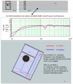
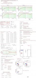
I've also attached the 2D rendering (shown without bracing). I created this design for a friend who bought a CSS SDX10 driver but he feel's it's too "big" for his space. Keep in mind that if you terminate the line just before the "tap" point, you have created a transmission line. I normally build an access panel a the tap point. With the access panel removed, the design acts like a TL. With it in place, it acts like a T-TQWT . See this for an example http://www.diyaudio.com/forums/atta...opinions-needed-tapped-horn-drivers-photo.jpg. Notice the difference in the folding technique in the last section compared to your attempt.
Hope this info helps.
Attachments
Last edited:
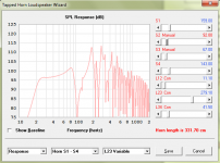
Here are some attempts with the TB W6-1139SIF driver Tang Band W6-1139SIF 6-1/2" Paper Cone Subwoofer Speaker 264-919 (assuming it will actually fit)
These kind of designs typically are only good for 2 to 2.5 octaves.
These kind of designs typically are only good for 2 to 2.5 octaves.
Attachments
Last edited:
- Status
- Not open for further replies.
- Home
- Loudspeakers
- Subwoofers
- TL sub under sofa