Thanks for the tutorial, I found it very helpful, as I'm sure many others will as well! 🙂
So I should be able to achieve a useable bw of 25-100 Hz then, which will be sufficient for both of my possible uses.
But what exactly are the benefits of going for T-TQWT versus my attempt in post #11? People seem to have differing opinions from what I can read in various forum threads...
These kind of designs typically are only good for 2 to 2.5 octaves.
So I should be able to achieve a useable bw of 25-100 Hz then, which will be sufficient for both of my possible uses.
But what exactly are the benefits of going for T-TQWT versus my attempt in post #11? People seem to have differing opinions from what I can read in various forum threads...
Thanks for the tutorial, I found it very helpful, as I'm sure many others will as well! 🙂
So I should be able to achieve a useable bw of 25-100 Hz then, which will be sufficient for both of my possible uses.
But what exactly are the benefits of going for T-TQWT versus my attempt in post #11? People seem to have differing opinions from what I can read in various forum threads...
In post 11, you presented a negative taper transmission line (TL). This is tuned to the quarter wave frequency of the pipe length. For example, if the pipe length is 3.4m, the design will be tuned to 340/(3.4 x 4) = 25 Hz.
On the other hand, if you make the negative taper TL design re-entrant (mouth taps into the driver , hence resulting in a T-TQWT), the eventual tuning frequency will be somewhere between the 1/4 wave frequency and the 1/2 wave frequency, .. perhaps somewhere around 20 Hz . Of course, you will need to design the T-TQWT properly but that's the general idea.
While I don't remember if T-TQWTs are more efficient than TLs or not,
one disadvantage of T-TQWT and TH are that they are limited in linear bandwidth i.e. the TL about might be able to operate well into the midbass depending on driver, stuffing etc but the tapped devices will basically operate for about 2 - 2.5 octaves. So a 20 Hz T-TQWT could potentially start behaving erratically above 80-100 Hz, depending on design. Of course, that should be irrelevant if they are used strictly as subwoofers.
Does that make sense ?
In post 11, you presented a negative taper transmission line (TL). This is tuned to the quarter wave frequency of the pipe length. For example, if the pipe length is 3.4m, the design will be tuned to 340/(3.4 x 4) = 25 Hz.
If I've got it right then this is the case for a straight line? The negative taper will allow a shorter line, right? Like my TL from post 11 which is 2.4m, with a tuning of about 23 Hz..
On the other hand, if you make the negative taper TL design re-entrant (mouth taps into the driver , hence resulting in a T-TQWT), the eventual tuning frequency will be somewhere between the 1/4 wave frequency and the 1/2 wave frequency, .. perhaps somewhere around 20 Hz . Of course, you will need to design the T-TQWT properly but that's the general idea.
While I don't remember if T-TQWTs are more efficient than TLs or not,
one disadvantage of T-TQWT and TH are that they are limited in linear bandwidth i.e. the TL about might be able to operate well into the midbass depending on driver, stuffing etc but the tapped devices will basically operate for about 2 - 2.5 octaves. So a 20 Hz T-TQWT could potentially start behaving erratically above 80-100 Hz, depending on design. Of course, that should be irrelevant if they are used strictly as subwoofers.
Does that make sense ?
Yep, thanks for the explanation. I tried to simulate my current design in hornresp but I came across another problem. As far as I can understand, Hornresp assumes (when selecting tapped horn in driver arrangement) that the rear of the driver is at S2, and the front of the driver is at S3? However, in my enclosure, I've got two sections after S2 before the front of the driver. Can I specify that the the front of the driver is at S4 rather than S3? Hope I explained that in a way that made it possible to understand... 😕
I'll attach a sketch to try and illustrate:

1.Yes, tapering a line down reduces the tuning frequency (or results in a shorter line for the same tuning frequency, compared to a straight line).If I've got it right then this is the case for a straight line? The negative taper will allow a shorter line, right? Like my TL from post 11 which is 2.4m, with a tuning of about 23 Hz..
Yep, thanks for the explanation. I tried to simulate my current design in hornresp but I came across another problem. As far as I can understand, Hornresp assumes (when selecting tapped horn in driver arrangement) that the rear of the driver is at S2, and the front of the driver is at S3? However, in my enclosure, I've got two sections after S2 before the front of the driver. Can I specify that the the front of the driver is at S4 rather than S3? Hope I explained that in a way that made it possible to understand... 😕
I'll attach a sketch to try and illustrate:
2. Please post your sim (a screenshot of the main page should suffice).
Thanks
2. Please post your sim (a screenshot of the main page should suffice).
This is the closest I can get.


This is the closest I can get.
...
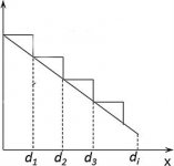
Hi, You can stop at 3 segments S1-S2, S2-S3, S3-S4 for this design. In such a case, the throat and mouth taps will be at S2 and S3 respectively.
No need to develop the S4-S5 segment. I see that you seem to have done it model the "linear stepped" model as closely as possible. It might be easier to just assume a linear taper and pick reasonable guesses for the segments. Maybe this illustration will helps. I'm not on my windows computer at the moment so can't illustrate with a concrete horn resp model and sketch.
Attachments
Can I specify that the the front of the driver is at S4 rather than S3?
Hi linaudio,
If a four segment TH tapped horn is specified, then the driver entry points will be at S2 and S4.
If the TH1 option is selected, the driver entry points will be at S2 and S3.
See the Tapped Horn section in the Hornresp Help file for further details.
Kind regards,
David
Hi, You can stop at 3 segments S1-S2, S2-S3, S3-S4 for this design. In such a case, the throat and mouth taps will be at S2 and S3 respectively.
No need to develop the S4-S5 segment. I see that you seem to have done it model the "linear stepped" model as closely as possible. It might be easier to just assume a linear taper and pick reasonable guesses for the segments. Maybe this illustration will helps. I'm not on my windows computer at the moment so can't illustrate with a concrete horn resp model and sketch.
Ok, I see. I'll try a bit of guesswork and give it a go in hornresp. Would be very interesting to see how you would approach a sim of this specific enclosure as well! 🙂
Hi linaudio,
If a four segment TH tapped horn is specified, then the driver entry points will be at S2 and S4.
If the TH1 option is selected, the driver entry points will be at S2 and S3.
See the Tapped Horn section in the Hornresp Help file for further details.
Kind regards,
David
Hi David,
Thanks, I see that now. I just assumed that it was at S3, seeing as S3 and S4 was in the same place in this case. 😛
And thank you for a great piece of software, I'm a still a newbie but learning every day! 😀
Ok, I see. I'll try a bit of guesswork and give it a go in hornresp. Would be very interesting to see how you would approach a sim of this specific enclosure as well! 🙂
BTW, .. if you want some proven examples of tapped horns (not TQWT), look at some of the 30Hz and 40Hz horn examples at Tapped Horns . He also describes tapped horn folding techniques at Download Section
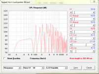
I tried fiddling with horn resp and came to the conclusion that this driver really wants to be in a tapped horn as opposed to a T-TQWT. I simulated a tapped straight line of sorts (lets call this a T-QWT). The probelm is that the driver will physically not fit. You might be able to change the sliders and find a compromise that will allow the driver to fit if you really wanted to. Compare these results to the TH with the same driver in the first link I provided.
Hope that helps.
Attachments
Last edited:
- Status
- Not open for further replies.
- Home
- Loudspeakers
- Subwoofers
- TL sub under sofa