How should I work with partial feedback so my stage does not clip and distort more than when there is no partial feedback? In spice this happens. Also it happens in one of my amplifiers. It seems to be normal.
I am running the feedback off of the power tube plates through a resistor to the plates of the output tubes to the phase splitter anodes.
I am running the feedback off of the power tube plates through a resistor to the plates of the output tubes to the phase splitter anodes.
Not gonna happen. It's one of the design trade-offs you make when applying NFB: clip behaviour deteriorates as the correction signal disappears when the output clips, driving the closed loop gain to the open loop figure, deepening the clip. You need more headroom to avoid nasty clipping, especially in the front end. Multiple stages that clip at once make for some ugly clip behaviour.
When I add the feedback, the phase splitter clips and distorts easier as I am running the output tube plates to the phase splitter plates.
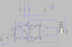
Adding R16 and R18 makes the phase splitter clip sooner (the lower the resistor value).
The problem with adding those feedback resistors is the increased loading of the driver. Think Miller Effect here: the effective value of the 47K feedback resistors is really:
47E3 / (1 + Av)
Given the 47K plate loads, you're cutting the effective plate load to much less than half. That's way too much, and I'm not surprised you have a premature clipping problem here. Given the lowish u-Factor of the LTP triodes, I'm surprised you're getting any gain at all.
This type of local NFB wasn't intended to do the whole job, but rather as a supplement to gNFB. That's how I applied local NFB where I needed it to tame the nasty harmonic signature of PP 807's. Holding it to 10% of the plate AC ( as recommended by O Schade ) reduced the loading effect to manageable proportions.
You already have lNFB with the Ultralinear connection. You don't need those feedback resistors, and certainly you don't need nearly 50% of plate feedback, especially when you have lNFB anyway.
Last edited:
To obtain the gain and distortion levels I want, I need 18dB of global feedback. With PPP quads, oscillation is more prone to occurring. With two tubes, it is usually fine. What is your thought of using that much global feedback?
The way I am computing the feedback is measuring the gain open loop and subtracting it from the closed loop gain. It comes out to be 18dB. Perhaps I am computing it wrong? In spice the numbers come out just fine without local feedback (assume 47k resistors are deleted).
To obtain the gain and distortion levels I want, I need 18dB of global feedback. With PPP quads, oscillation is more prone to occurring. With two tubes, it is usually fine. What is your thought of using that much global feedback?
18db of gNFB is excessive. I found that using 12 db in one project with variable gNFB was definitely tending towards a solid statey sound. For another, 20db was positively hideous, and made the project sound no better than a run of the mill solid state rig. I don't use much more than 6 or 7 db of gNFB for either. Just enough to take off the "edge".
I would ditch either the parallel NFB or the Ultralinear: one or the other, but not both. I would also get rid of that SRPP. That's a fad topology that isn't being used the way it was intended, and you'll get more gain for gNFB if you use an active plate load for the 12AY7. That will also improve the linearity as well, beyond what you'd get from an SRPP.
I would also include an active tail load for the LTP. If you include that, you won't need to unbalance the plate loads, with the resulting compromise in high frequency behaviour.
I would try for ~7.0db of NFB and give a listen. If you did the open loop design properly. you won't need much more than that, and too much will definitely sound "off".
Last edited:
The way I am computing the feedback is measuring the gain open loop and subtracting it from the closed loop gain. It comes out to be 18dB. Perhaps I am computing it wrong? In spice the numbers come out just fine without local feedback (assume 47k resistors are deleted).
You are figuring it wrong. The formula is:
Avol/Avcl= 1 + BAvol= 20log[1 + BAvol] (in voltage db)
Where:
Avol: open loop gain
Avcl: closed loop gain
B: voltage division ratio of the feedback network.
log: Radix 10 logarithms
So you suggest making the top triode a CCS rather than an SRPP? Interesting.
In this design, the LTP is a 12BH7A with a u-Factor of: u= 16.5 (nominal). It doesn't provide very much gain, and as an LTP, you lose half of whatever gain you can get with passive plate loading. Assuming a reasonable 60% of u: Av= ~5 -- 6 V/V. That ain't much, even without any gNFB at all.
You're going to have to make it up in the pre, and since the 12AY7 has a u-Factor of 44 (nominal) it can be done, but will need either active plate loading with a solid state CCS. You could also use bootstrapping since you're already using a dual triode. Either way will give nearly u-Factor voltage gains that can make up for the low gain of the LTP, and allow for reasonable input sensitivity and gNFB levels.
The formula for finding the closed loop gain yields a closed loop gain of around 17.5 (25dB) I measure 106 for the open loop gain in spice (about 40 dB). Subtracting the two yields 15dB. I think I still am mixed up somewhere.
What GF Db gain number did you compute so I can find where I am mixed up? The spice project is attached
What GF Db gain number did you compute so I can find where I am mixed up? The spice project is attached
Attachments
I measure 106 for the open loop gain in spice (about 40 dB).
I highly doubt that. From the KT88 spec sheet:
Rl= 6K (P-2-P)
Po= 50W
That gives:
V^2= PR
sqrt[(50)(6E3)]= 547.72Vrms (across the whole primary)
547.72/2= 273.86Vrms (across half, so each KT88 has a voltage gain of about 5.78 V/V)
Given that you're taking the gNFB off the 16R secondary:
Zr= 6000/16= 375
Vr= sqrt(Zr)
Vr= sqrt(375)= 19.37
This is a voltage step-down, and so 28.28Vrms is the output voltage that will be divided down at the gNFB summing node. With an 8R load, the Vo= 20Vrms at the 8R secondary tap-off. This is the output you need to figure your open loop gain, and that OPT with its voltage drop ratio means that the final has less than unity gain. As for figuring the gNFB, you need to know what your expected input is in order to determine the required input sensitivity to drive it to full output. Assuming that's 1.0Vrms, the closed loop gain should be at least 20 from input to speaker out.
I'd guesstimate an Avol= 80, given the front end VT line-up. The bare minimum of input sensitivity would give:
20log(80/20)= 12.84db of gNFB.
You might use that much, but cutting that back a bit would help the sensitivity, and might not sound so solid statey. 7.0db of gNFB would let you have Avcl= 35.73, and your input sensitivity would be: 0.56Vrms for full power.
You have a number of problems.
You will have massive distortion because the 47K anode load resistors on the 12BH7 are anti-bootstrapped and will look nothing like 47K, probably more like 10K.
That is due to way too much "partial" feedback. You do not see all the effect of that feedback as it is divided down by the low rp of the 12BH7 triodes.
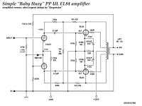
I had to come to grips with all this stuff when I did the Baby Huey design.
You need low current and high rp for the triodes in the phase splitter. 12BH7 is not the right choice. You need 12AX7 or even a pair of pentodes instead. Look for the Baby Huey Wiki that Bas has put together and see how to use shunt feedback from the output tube anodes.
Cheers,
Ian
If you use balance shunt feedback and Ultralinear connection it is very doubtfull that you will need any global feedback at all.
Cheers,
Ian
You will have massive distortion because the 47K anode load resistors on the 12BH7 are anti-bootstrapped and will look nothing like 47K, probably more like 10K.
That is due to way too much "partial" feedback. You do not see all the effect of that feedback as it is divided down by the low rp of the 12BH7 triodes.
I had to come to grips with all this stuff when I did the Baby Huey design.
You need low current and high rp for the triodes in the phase splitter. 12BH7 is not the right choice. You need 12AX7 or even a pair of pentodes instead. Look for the Baby Huey Wiki that Bas has put together and see how to use shunt feedback from the output tube anodes.
Cheers,
Ian
If you use balance shunt feedback and Ultralinear connection it is very doubtfull that you will need any global feedback at all.
Cheers,
Ian
- Status
- Not open for further replies.
- Home
- Amplifiers
- Tubes / Valves
- Partial Feedback System