Now i have my 110db+ sensitive horn setup i am getting some 50Hz hum. I have disconnected everything upstream and it remains there. Is it realistic to get zero hum?
ZM will ask to post photos, so you can impress him and post good photos of your amp and PSU especially, before he asks ;-)
Try twisted pairs for EVERY flow and return pair.
Ensure there is NEVER a flow wire separated from it's return.
This may or may not improve your hum.
But before you start modifying, measure the amplifier output noise and output offset with the input shorted (0r) and with a 1k0 as the dummy input source.
Then you have something to compare with after the modification/s
If all this fails to give a significant improvement, then try the CRC or CLC as the smoothing.
I added ~47uH between the first and second caps and got an ~10dB reduction in ripple on the PSU output.
if Iq is in area of regular FW Aleph J (say 80W of dissipation per channel ) then 4x22mF is on lowish side
NP is using 8x15mF in common FW PSU
that fact , combined with not perfect wiring and super efficient spks is what is giving that buzz
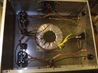
also - it seems you have sort of separate C banks for each channel which isn't optimal solution , just because they're anyway in parallel , due to common connection at Graetzs
so - either put them (caps) together , physically close , and wire them properly ...... in CRC , then route wires to channels , or make separate channel C banks with each bank having own pair of Graetzs
choice is yours
NP is using 8x15mF in common FW PSU
that fact , combined with not perfect wiring and super efficient spks is what is giving that buzz
also - it seems you have sort of separate C banks for each channel which isn't optimal solution , just because they're anyway in parallel , due to common connection at Graetzs
so - either put them (caps) together , physically close , and wire them properly ...... in CRC , then route wires to channels , or make separate channel C banks with each bank having own pair of Graetzs
choice is yours
I have a big box of 25000uf caps i bought on here and will redo into CRC and put them close together.
Thank you all for your help, again
Thank you all for your help, again
Um, it seems that the green wire at the capacitor bank is ground, right? If so, massive ground loop right there.
How? Right input ground going to pcb. Ground wire going to right cap bank. From there to left cap bank. From there to pcb and to the left output. The two channels' grounds inevitably meet somewhere, and thus a massive loop is formed. And the transformer sitting right in the middle of it all.
If there's one thing I loathe, it's ground loops. So help me sleep better, and break the loop (but still ground everything properly!). You should see some improvement by doing so.
Correct me if I'm wrong but your transformer seems to have a three wire secondary, and you seem to have two bridge rectifiers one for each amplifier board not so? In a form of dual mono power supply but from a common transformer, in my limited experience when trying this scheme always resulted in hum, try using one bridge rectifier for both boards and just use your existing caps for the smoothing, worth a try. And as Andrew T said twisted pairs, always.
Wazzy - Good eyes! Bravo!
3GGG - Wazzy's suggestion is spot on - use one bridge to feed the PSU, like this - (please excuse the crude sketch)
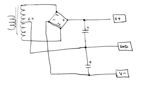
3GGG - Wazzy's suggestion is spot on - use one bridge to feed the PSU, like this - (please excuse the crude sketch)
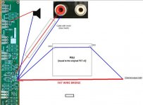
Thank Mod Zen for the wiring diagramm of the ground. In summary:
1) Main Audio Ground "L" and "R" are on the amp boards.
2) The power thermistor between MAG and chassis.
3) With Arta verify if the FAT WIRE BRIDGE lowers the noise.
1) Main Audio Ground "L" and "R" are on the amp boards.
2) The power thermistor between MAG and chassis.
3) With Arta verify if the FAT WIRE BRIDGE lowers the noise.
will the Power Thermistor pass Fault Current?...........
2) The power thermistor between MAG and chassis..............
That Fault Current can approach and even exceed 1kApk.
I do not understand. Under ordinary condition the thermistor provides some isolation against ground loops. If the leakage becomes large current, then the thermistor heats up, providing a more efficient path. Why it is not a good solution? It best to connect the thermistor between the PSU and chassis?
Thank you for your patience.
Thank you for your patience.
power thermistor will certainly pass greater current than fuse , be it on secondary or primary side
if that's good solution for PL and FW products , which certainly have all necessary trading/safety/regulatory permissions ..........
if that's good solution for PL and FW products , which certainly have all necessary trading/safety/regulatory permissions ..........
are you sure?power thermistor will certainly pass greater current than fuse , be it on secondary or primary side ..........
a fault current prior to the fuse blowing can be 1kApk.
Can a Power Thermistor pass this current?
Or will the power Thermistor reduce the current such that the fuse does not rupture?
Have you tested any Power Thermistor to see if they survive longer than it takes for the fuse to rupture and the arc to extinguish?
- Status
- Not open for further replies.
- Home
- Amplifiers
- Pass Labs
- Slight 60 Hz hum Aleph J