Again, ion bombardment is not the issue for cold start grid-to-cathode, it's arcing you need to worry about.
In the worst case, 2MV/m are under vacuum rupture eg from 20 MV/m to 40 MV/m.
I swear I did not find a damn data for the distance between cathode and anode.
However, in Toshiba's paper fig.7, ion bombardment starts at something like 100eV, not to say wow, but Ion bombarment stops being a ghost.
🙂
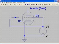
Practical circuit and protection for a DC coupled cathode follower. I could write an essay but Merlin says it all. This circuit is used in a lot of guitar amps, particularly for driving the tone controls.
The Valve Wizard
Cheers,
Ian
The Valve Wizard
Cheers,
Ian
I found neon lamps of the smaller type of about 55-60V for use as voltage references in a strange circuit I designed the past 2012.
He, he, I have experimental evidence of ion bombardment at about 100 eV. 😉
A frequent cause of lost of emission in cathodes, is the formation of a coating produced by sputtering.
Unfortunately, the paper of post # 31, is no longer available, those who can pay for it, you can buy at
ScienceDirect.com - Vacuum - Emission characteristics and surface composition of dispenser cathodes in realistic vacuum
In CRTs, you fight fire with fire, the coating is removed by ion bombardment, with the experimental device of the figure attached.
I used to use something like 300 V, just out of curiosity I started to reduce the voltage, and surprise ! at 150V the results are better and more durable long-term.
At 100V, the results are good, but the process must be repeated at least twice, a lot of work for a poor TV repairman.
Conclusion: Cathode stripping is real, even more, it happens with amazingly low voltages ! 😎
If I were the cathode, I would continue praying, now louder... 😀
Attachments
I'd be suggesting that operating each valve with a significant cathode-heater bias (first stage with cathode negative; CF stage with cathode positive) may each possibly achieve a tangible hum benefit from increased cathode-heater insulation resistance. The insulation resistance increases with bias voltage magnitude away from zero. The reference indicates how variable the magnitude of cathode-heater insulation can be on a sample by sample basis, and how much of a misnomer the 'diode' characteristic is.If you elevated the heaters to +75V relative to ground then they would be -190 +75 = -115 relative to the CF cathode - well within the 200V spec and with plenty of headroom for large signals. They would also be +75 - a bit above the other cathode, again well within the 100V spec. The other advantage of the heaters being +ve with respect to the first cathode is that the diode formed by the heaters and the cathode is now reverse biased which eliminates one form of hum pickup.
Heaters section by Dingwall in the RCA 1962 Electron Tube Design book:
Electron Tube Design : Radio Corporation of America : Free Download & Streaming : Internet Archive
He, he, I have experimental evidence of ion bombardment at about 100 eV. 😉
Conclusion: Cathode stripping is real, even more, it happens with amazingly low voltages !
Surely ionisation can occur all the way down to the ionisation potential of the gas? (which is about 20V for oxygen).
But CRT cathodes are operated with high saturation current densities, very different from receiving tubes. There is not a shred of evidence to suggest a delayed warm up is beneficial to the cathode life of a receiving tube. If you have some, please share! 🙂
first you talk about Vak then Vgk😕Maybe this is not unrelated, and it is only to describe the phenomenon
http://144.206.159.178/FT/68/73201/1254249.pdf
A CRT has indirectly heated cathode, then the extrapolation is valid, at least in first approximation, to an ordinary vacuum tube.
By definition
E = - ∇φ = dφ/dx
Integrating
V = Δφ = ∫dφ = E ∫dx = E d
Then
E = V/d
For a 20-inch CRT, as I see daily
Vak ≈ 25 KV dak ≈ 40 cm Vg1 = 0 V
Then
Eak ≈ 62.5 KV/m 😉
For 12AU7
Vgk ≈ 40 V (DF dixit) dgk ≈ 0.17 mm *
Then
Egk ≈ 235 KV/m 😀
* History of Electron Tubes - Google Libros
For WE416C
Vgk ≈ 40 V dgk ≈ 20 µm (Morgan Jones dixit)
Then
Egk ≈ 2 MV/m
Well, after all I am not so coward. 😎
And if I were the cathode, would continue praying. 😀
Well, energy is another matter, but can not deny that the numbers scare. 😀
Surely ionisation can occur all the way down to the ionisation potential of the gas? (which is about 20V for oxygen).
Ionization and then ion bombardment depends on the energy-momentum of the electrons.
What you say is in theory possible, however, for such low energies the probability of an event is too low, and the electron cloud make things even more difficult.
But CRT cathodes are operated with high saturation current densities, very different from receiving tubes. There is not a shred of evidence to suggest a delayed warm up is beneficial to the cathode life of a receiving tube. If you have some, please share! 🙂
In metals, at normal temperature, the conduction band is essentially filled of electrons only up to the Fermi energy EF, to extract an electron from the metal is therefore necessary to give a starting energy eφ, but at high temperatures the occupation of electronic states extends above EF.
If the temperature is high enough, some electrons reach energies greater than EF + eφ, and escape from the metal.
eφ = E - EF
Where
E is the total energy of the electron
EF is the Fermi energy
φ is the work function of the metal
e is the charge of electron
Since electrons are fermions, using the Fermi-Dirac distribution to calculate the number of electrons that reach the surface of the metal with enough energy and proper motion direction to escape, we can obtain the thermoelectric current density leaving metal surface as a function of its temperature T.
The result is known as Richardson-Dushman equation and has the form
Jo = Ao T^2 exp ( - eφ / k T )
Where
Jo is the emission current density
Ao is the Richardson constant
k is the Boltzmann constant
T is the absolute temperature of the metal
Ao = 4 π m e k^2 / h^3
Where
e is the charge of electron
m is the mass of electron
h is the Planck constant
Applying an accelerating potential Va, to a sufficiently high value thereof, the current density reaches the saturation value of Js, then it can be shown that
Js= Jo exp ( e Va / k T )
Wow !
What tou say is true, for CRTs, Va ≈ 25 KV, and saturation current density is very high !

Oops, the device of attachment on post # 44 uses only Va ≈ 100 V, not so high saturation current density, try another objection, please. 🙂
Last edited:
Erratum: the work function of the metal, is eφ. 🙂
.........................................................................................................
If you had read, in post # 39 and post # 41, I already made clear that I did not find any data for the distance between cathode and anode.
.........................................................................................................
first you talk about Vak then Vgk😕
If you had read, in post # 39 and post # 41, I already made clear that I did not find any data for the distance between cathode and anode.
The numbers were suggested by DF, Vgk = 40 V instead of 90 V or so.
There's a guy out there that broke an ECC82, and found dgk = 1/20 mm, I found a book with dgk = 0.17 mm.
For WE416C, the very Morgan Jones says dgk = 20 µm.
For a 20 inch CRT, dak measured myself with a tape measure, and I've had some close encounters with Vak = 25 KV, ouch !
I swear I did not find a damn data for the distance between cathode and anode.
- Status
- Not open for further replies.
- Home
- Amplifiers
- Tubes / Valves
- Elevated Heater Question