how about 4 x 9Vac
you can always do a 2 x 18Vac
If you can arrange It there will be much people Involved and price will be lower
Sorry, but that would make me need two transformers which wouldn't fit my case. And since i would need two transformers price would probably be cheaper - but not for me, since would need to more than half the price for it.
i'll be ordering custom r-core from vt4c 🙂
Batteries discharged
I have 4 x 9V NiMH batteries, and I get 2 x 18V when I put in series, and I can to fed each channel with 18V.
Batteries are of 9V 280 mAh and I build the Xen-Audio charger following the design criteria I saw in a Excel sheet.
Two batteries has an R of 22 ohm and a relay and a voltage regulator with 17,2V at Output for charging.
I have checked this connections and all seems OK, but allways get the batteries totally discharged in a day.
I will try rising the charging voltage ...😕
> but allways get the batteries totally discharged in a day ....
I don't quite understand what you mean.
You leave the SEN on all day ? Or you cannot recharge within 24 hours ?
If you are using 2SK369V, your total consumption is about 40mA per SEN circuit (half the PCB).
So 280mAh will last 7 hours at most. So if you leave it on all day, surely it will be totally discharged.
NiMH does not like over-discharged.
And your batteries would probably be not in perfect shape by now if you would have repeatedly leave it on all day.
The charging circuit published is slow charge, meaning that you need ~20 hours till fully recharged.
Then those 9V NiMH batteries have a nominal voltage of 8.4V. When fully charged they would be 9.8V.
So according to the excel sheet, you should be using 20V voltage regulator followed by a 57R resistor when you have 2 of these in series.
Patrick
Ouch!> but allways get the batteries totally discharged in a day ....
I don't quite understand what you mean.
You leave the SEN on all day ? Or you cannot recharge within 24 hours ?
If you are using 2SK369V, your total consumption is about 40mA per SEN circuit (half the PCB).
So 280mAh will last 7 hours at most. So if you leave it on all day, surely it will be totally discharged.
NiMH does not like over-discharged.
And your batteries would probably be not in perfect shape by now if you would have repeatedly leave it on all day.
The charging circuit published is slow charge, meaning that you need ~20 hours till fully recharged.
Then those 9V NiMH batteries have a nominal voltage of 8.4V. When fully charged they would be 9.8V.
So according to the excel sheet, you should be using 20V voltage regulator followed by a 57R resistor when you have 2 of these in series.
Patrick
I put 12 cells (16,8V fully charged), 560 mAh (280+280) and get 17,2V.. !!!
I see that i was wrong
Well i will try with 20V and 57R
Thanks Pratrick !
57R is for 2x 9V batteries wired in series to give 18V.
For 4 batteries, you need to use two separate 57R resistors.
Do not wire the two sets of batteries in parallel during charging.
Patrick
For 4 batteries, you need to use two separate 57R resistors.
Do not wire the two sets of batteries in parallel during charging.
Patrick
Elsewhere the SEN IV has been accused of having poor or no PSRR.
http://www.diyaudio.com/forums/digital-source/232940-pcm1704-nos-strange-clipping.html#post3431830
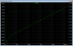
I wanted to find out for myself, so I did some quick simulation using my proven Spice models.
The input current was set to zero, and a 2V pk-pk noise voltage was added to the PSU.
The output is then plotted against frequency.
The first graph belongs to the SEN V18 for ES9018, using 2SK369Vs.
This is the worst of all variants, due to the higher capacitances of the 2SK369's.
Still, I personally would not consider -42dB at 100kHz to be poor PSRR.
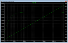
The second graph belongs to the Cascoded SEN for PCM1704, using J111 cascoded BF862s.
I do not consider PSRR of -66dB at 1MHz to be any issue at all.
Most of your output noise will come from the digital noise of the DAC, not the IV PSU.
Unless of course you have really poor power supplies with huge ripples at HF.
Cheers,
Patrick
http://www.diyaudio.com/forums/digital-source/232940-pcm1704-nos-strange-clipping.html#post3431830
I wanted to find out for myself, so I did some quick simulation using my proven Spice models.
The input current was set to zero, and a 2V pk-pk noise voltage was added to the PSU.
The output is then plotted against frequency.
The first graph belongs to the SEN V18 for ES9018, using 2SK369Vs.
This is the worst of all variants, due to the higher capacitances of the 2SK369's.
Still, I personally would not consider -42dB at 100kHz to be poor PSRR.
The second graph belongs to the Cascoded SEN for PCM1704, using J111 cascoded BF862s.
I do not consider PSRR of -66dB at 1MHz to be any issue at all.
Most of your output noise will come from the digital noise of the DAC, not the IV PSU.
Unless of course you have really poor power supplies with huge ripples at HF.
Cheers,
Patrick
Attachments
The problem with the cen and sen is the common noise rejection ratio that is zero .
The numbers that you present is the measure of the diferential noise rejection ratio.
One must have very careful in choose the power transformer , separate coils is a must .There are some exemples of common noise supression filters in the internet.
http://www.murata.com/products/emc/knowhow/pdf/26to30.pdf
I know it's difficult to read everything in these long threads, but there have been extensive discussions of these issues, including schematics and specifications of common-mode chokes.The problem with the cen and sen is the common noise rejection ratio that is zero .
The numbers that you present is the measure of the diferential noise rejection ratio.
One must have very careful in choose the power transformer , separate coils is a must .There are some exemples of common noise supression filters in the internet.
http://www.murata.com/products/emc/knowhow/pdf/26to30.pdf
I have been advocating the use of batteries for the SEN / CEN since day one. So I have to admit I don't understand the problem.
In our own IV (using batteries), it is so dead quite, that you cannot hear anything at max. volume even with headphones.
If one insists on using transformers, Joachim Gerhard also posted a schematics for a floating supply with common mode choke before.
http://www.diyaudio.com/forums/digi...-minimalistic-iv-converter-9.html#post2769085
http://www.diyaudio.com/forums/digi...minimalistic-iv-converter-11.html#post2871056
But as Nic found out, batteries are still better.
In any case many thanks for the link to the Murata article.
Very good reference.
🙂
Patrick
Last edited:
Patrick,
After many months (years?) I have decided I really must put my Sen V18 together; so looking at everything I have one question springs to mind.
I have the pack of matched jfets and associated document which details Channel against Upper / Lower; other documentation refers to Q1 thru Q4 with Q1/Q3 and Q2/Q4 being thermally coupled.
Would I be correct in thinking that Q1/Q2 form the Upper set whilst Q3/Q4 form the Lower?
There is a second question! I have the heat sinks for two jfets, should I thermally couple the heat sinks for q1/q3 and q2/q4?.
Alan
Alan,
The transistor designations are indicated on the PCB.
Q1/Q2 are the upper pair, Q3/4 the lower.
Thermally the upper should track the lower.
So heatsinks are for Q1/Q3 & Q2/Q4.
You actually figured out all the answers already. 🙂
Patrick
The transistor designations are indicated on the PCB.
Q1/Q2 are the upper pair, Q3/4 the lower.
Thermally the upper should track the lower.
So heatsinks are for Q1/Q3 & Q2/Q4.
You actually figured out all the answers already. 🙂
Patrick
Hello,
sorry to hijack this thread, but i had a quick question. I've simulated the SEN with paralleled BF862's, results are attached. I thought distortion would be lower. Could please somebody check if I've done something wrong?
Thanks,
Peter
sorry to hijack this thread, but i had a quick question. I've simulated the SEN with paralleled BF862's, results are attached. I thought distortion would be lower. Could please somebody check if I've done something wrong?
Thanks,
Peter
Attachments
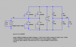
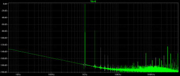
I spiced the same circuit as yours without the R4 and got :
2nd harmonics 2.1e-5
3rd harmonics 1.9e-6
4th harmonics 1.5e-6
In general BF862 has a higher dependence of Id on Vds, so best used when cascoded.
See :
http://www.diyaudio.com/forums/digi...minimalistic-iv-converter-28.html#post3393695
http://www.diyaudio.com/forums/digi...minimalistic-iv-converter-28.html#post3393714
"Cascoded SEN using BF862 cascoded with J111"
Patrick
Thanks for your quick reply.
Without R4, the distortion levels are slightly better. Would it mean that the SEN does not like the PCM1704's lowish output impedance? The CEN with SK170/SJ74 sims way better.
Peter
PS: Forgot to mention that cascoding didn't help with R4 present.
Without R4, the distortion levels are slightly better. Would it mean that the SEN does not like the PCM1704's lowish output impedance? The CEN with SK170/SJ74 sims way better.
Peter
PS: Forgot to mention that cascoding didn't help with R4 present.
Thanks for your quick reply.
Without R4, the distortion levels are slightly better. Would it mean that the SEN does not like the PCM1704's lowish output impedance? The CEN with SK170/SJ74 sims way better.
Peter
PS: Forgot to mention that cascoding didn't help with R4 present.
For good sim results, try #1375 with more parallel pairs to get the input impedance down. Not sure if anyone has actually listened to #1375 working though...
I am not sure whether a current source in parallel with a 1k resistor represents the PCM1704 correctly.
And simulation is only a tool, not reality.
Patrick
And simulation is only a tool, not reality.
Patrick
I'll try both SEN and CEN this weekend, and post the results.
I completely agree with your opinion regarding validity of simulations. The only thing what bothers me is that reality is almost always worse than simulation.
Patrick, did you try SEN with PCM1704 yourself? If yes, what performance did you achieve?
Peter
I completely agree with your opinion regarding validity of simulations. The only thing what bothers me is that reality is almost always worse than simulation.
Patrick, did you try SEN with PCM1704 yourself? If yes, what performance did you achieve?
Peter
There are tricks to the PCM 1704. One is doubling them up, twice the current even thuogh it halves the output impedance seems to help. The other thing that is a must is large caps for BPO and DC servo pins, this makes it sound more like a PCM63.
My problem with the Sen is the batteries, I am just too absent minded. I thought about 4x Li-ion 18650 batteries, these are 4.7V each fully charged, have a much lower output impedance than NiCad. But you have to charge them individually which is a pain. I used LiFePO4 batteries on one project but blew it up when I inserted the battery backwards!
Has anyone thought a bout using a rechargeable drill battery and charger? 18V is a common Voltage for these. Could fab a socket on the chassis and just plug it in, swap a pair back and forth. Would look silly but it would be practical.
- Home
- Source & Line
- Digital Line Level
- Zen -> Cen -> Sen, evolution of a minimalistic IV Converter