Hi guys hope you can help me with this one.
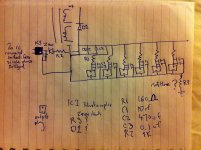
I have a Soundlabs six channel 9v dc power supply for guitar Pedals. Pre warning I'm still a beginner, so sorry if the way I explain things is hard to understand, I'm still learning. Also I apologise for my bad circuit drawing. I kinda guessing at the tranny setup up there so ignore my circuit symbol for that.
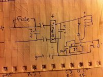
I want to clean the power up a bit with either some rectification or maybe even a tranny replacement. I have 2X in5817 2x in5816 and 2x in5819 diodes.
-Could I put one in parrallel after the diode (d1) thats already there? then change the 10uf (c1) cap to 470uf so it's the same as (c2).
-There's a resistor (r3) that has been removed from negative to ground? I guess by the manufacturer as a revision. I guess thats got something to do with rfi should I put something in there?.
-Anything I can do to prevent ground loops between pedals?
-would replacing the rectifier with a better one help as well.
Had to draw the circuit in two goes sorry hope it maks sense.
I have a Soundlabs six channel 9v dc power supply for guitar Pedals. Pre warning I'm still a beginner, so sorry if the way I explain things is hard to understand, I'm still learning. Also I apologise for my bad circuit drawing. I kinda guessing at the tranny setup up there so ignore my circuit symbol for that.
I want to clean the power up a bit with either some rectification or maybe even a tranny replacement. I have 2X in5817 2x in5816 and 2x in5819 diodes.
-Could I put one in parrallel after the diode (d1) thats already there? then change the 10uf (c1) cap to 470uf so it's the same as (c2).
-There's a resistor (r3) that has been removed from negative to ground? I guess by the manufacturer as a revision. I guess thats got something to do with rfi should I put something in there?.
-Anything I can do to prevent ground loops between pedals?
-would replacing the rectifier with a better one help as well.
Had to draw the circuit in two goes sorry hope it maks sense.
Attachments

Its hard to tell what's going on there with your diagram. It can't work like that. The bridge rectifier is on the wrong side of the transformer
Putting individual regulators on each output can help alot with the noise and interaction between the pedal's power rails. Replacing the transformer and/or rectifier would likely do nothing to help in those regards.
I agree with counter culture, the diagram doesn't make any sense, so it's hard to get specific.
I agree with counter culture, the diagram doesn't make any sense, so it's hard to get specific.
Putting individual regulators on each output can help alot with the noise and interaction between the pedal's power rails. Replacing the transformer and/or rectifier would likely do nothing to help in those regards.
I agree with counter culture, the diagram doesn't make any sense, so it's hard to get specific.
I read in another forum replacing the chip with a lm317 reduced noise. It's a voltage regulator but I can't see where it would go.
Last edited:
Short answer, don't touch it.
Sorry.
Get help from a friend who has some experience.
I thought that is what this place is for. Sorry I've never traced a circuit out before. I've only ever had to replace parts.
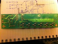
Someone posted this on another forum
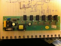
"That last photo reveals all. This is what is called a switch-mode power supply. These may look simple but are in fact hideously complex. I've worked in the trade for over 40 years and avoid messing with these things like the plague! It is very unlikely you'd be able to improve it's performance, and the change you suggest would result in a rather big bang! That chip is the switching control chip (which unusually appears to directly drive the transformer).
The input reservoir cap and the output filter cap both look to be in good condition so it's unlikely that there is any mains hum being produced by this unit. Also, like most such power supplies the unit completely isolates the output from the mains - not even earthing it, so it won't be causing any earth loops. That is, unless there is an earth connection elsewhere in the box. "
OK, it appears to not have any regulation, just simple RC filters on each output. Is the problem you're having with a bunch of hiss noise in the outputs? Switch mode supplies are sometimes very noisy, though I've noticed most of ones designed to work with guitar pedals (like the Visual Sound OneSpot), seem to not be bad in that regard. If you're having noise problems, I would guess the filtering in this one is inadequate.
You could measure the output voltage and see what it is. To get an accurate reading, you should have a pedal plugged into one of the outputs and powered up so the power supply has a load. Measure the DC voltage across C18, that small cap near the transformer. This should tell you how much voltage is present before the output filters. My guess is somewhere in the neighborhood of 10-12v. If you have in the range closer to 12, you should have enough voltage to work with to be able to stick a regulator in there somewhere and possibly help with the noise problem. If you only get about 9v at that spot, you wouldn't be able to use most regulators to get 9v out of it, because they usually need approximately 1,5v over the desired voltage to get proper regulation.
You could measure the output voltage and see what it is. To get an accurate reading, you should have a pedal plugged into one of the outputs and powered up so the power supply has a load. Measure the DC voltage across C18, that small cap near the transformer. This should tell you how much voltage is present before the output filters. My guess is somewhere in the neighborhood of 10-12v. If you have in the range closer to 12, you should have enough voltage to work with to be able to stick a regulator in there somewhere and possibly help with the noise problem. If you only get about 9v at that spot, you wouldn't be able to use most regulators to get 9v out of it, because they usually need approximately 1,5v over the desired voltage to get proper regulation.
Hi guys hope you can help me with this one.
I have a Soundlabs six channel 9v dc power supply for guitar Pedals. Pre warning I'm still a beginner, so sorry if the way I explain things is hard to understand, I'm still learning. Also I apologise for my bad circuit drawing. I kinda guessing at the tranny setup up there so ignore my circuit symbol for that.
I want to clean the power up a bit with either some rectification or maybe even a tranny replacement. I have 2X in5817 2x in5816 and 2x in5819 diodes.
Is there anything wrong with the output? Noise? If so what kind of noise?
-Could I put one in parrallel after the diode (d1) thats already there? then change the 10uf (c1) cap to 470uf so it's the same as (c2).
No reason to touch the diode. Don't touch the 10uF cap until you check the datasheet of the IC for what exactly the cap does.
The cap that is on the right of the transformer, you can increase the capacitance slightly and use a low-ESR type from a good manufacturer. (My favorite is Panasonic FM.)
-There's a resistor (r3) that has been removed from negative to ground? I guess by the manufacturer as a revision. I guess thats got something to do with rfi should I put something in there?.
To tie the secondary to ground. To ground or not to ground... that's a trial-and-error in audio.
-Anything I can do to prevent ground loops between pedals?
-would replacing the rectifier with a better one help as well.
Usually achieves nothing.
Had to draw the circuit in two goes sorry hope it maks sense.
And also, this power supply is regulated. Because photocoupler.
So because it's regulated putting in a lm317 is pointless?
Depends. You won't get much more in terms of voltage regulation - maybe the SMPS does 10% while the linear regulator afterwards does 0.1%. But what comes out from the linear regulator will be much cleaner than the SMPS feeding the linear reg. Some PC sound cards generate 5V using a linear reg and the computer PSU's 12V, even though the computer PSU also provides 5V.
But the linear reg's output needs to be at least (dropout voltage + 0.5V to 1V of headroom to filter out the ripple + noise from the SMPS) lower than the input to be effective. So if your equipment can live with 7V it'd be fine.
I like to get a cheap external SMPS of higher voltage (say, 19V which is cheap because it is laptop power supply), then regulate it down to whatever I need with a linear reg. Cheaper than using 50Hz transformer (and cheaper than getting a power brick of the required voltage too), but most importantly I won't have to deal with the danger of making sure my DIY-ed equipment is capable of housing 230V.
That's why I'm curious as to what the voltage is before the filters. It may be high enough to regulate down to 9v.
Improving the main filter cap is good suggestion.
Improving the main filter cap is good suggestion.
The outputs appear to have LC filtering,the voltage before them will be more-or-less the same as the output. (The DC Resistance of the coils is low,so there's not a large voltage drop across them.)
Also, this appears to be 'positive ground' or a -9V supply. (The inside 'tip' of the jacks is negative,and the outer barrel,or 'ring', is positive. Thus,the LC filters are in the negative side of the circuit -this may be a cause of ground loops.)
Also, this appears to be 'positive ground' or a -9V supply. (The inside 'tip' of the jacks is negative,and the outer barrel,or 'ring', is positive. Thus,the LC filters are in the negative side of the circuit -this may be a cause of ground loops.)
Last edited:
I think the OP should consider building himself a new supply from scratch. It would be a better learning experience.
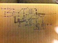
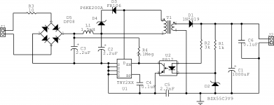
As i see it is TNY or Vipper chip. Something like that in the attached picture.
There is regulation through optoisolator and zener. Every output is filtered by LC.
Looks good but it is not. These chips work with jitter frequency around 120 kHz. This produce wide spectrum but with lower energy than fixed frequency easy to filter ... whatever.
Your problem is the blue capacitor in your board (C5 in my circuit). All smps need such capacitor to work, .... it will take time to explain why.
DON'T TOUCH, REMOVE OR REPLACE HIM!
The smps can't replace old good transformer power supply in all cases. I had once similar problems with infrared FM transmitter (95kHz, 25kHz deviation).
Worked only with classic power - transformer, Graetz (with capacitors around diodes), electrolyte and 78 whatever you want regulator. Just try one of the kind.
Attachments
Would changing the main filter cap to 1000uf instead of 470 help. Someone one on another forum ran a simulation and said it filtered out down to 16hz
That's why I'm curious as to what the voltage is before the filters. It may be high enough to regulate down to 9v.
Improving the main filter cap is good suggestion.
After the resistor but before the caps?
- Status
- Not open for further replies.
- Home
- Amplifiers
- Power Supplies
- Help cleaning up ripple on 9v 6 chnl guitar pedal power supply