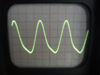
Also, make a frequency sine sweep with the generator - from 1K to 100K Hz - and look for variations in the level of the output. Usually there is a resonance around 50KHz.
Sinus 50KHz loaded with 100K
Attachments
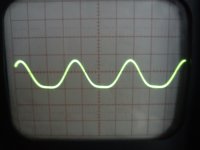
Sinus 50KHz loaded with 100K
Felipe,
I do not want pictures, just look for the level of the sine wave as you move the frequency from 1kHz to 100KHz
Oki. Some 26 builder has to comment on the squares. Did you listen yet?
They don' t look much different in mine.
I used an RC at the output to damp the ringing a bit.
I do not know though how they look with another transformer than the LL1660.
Oki. Some 26 builder has to comment on the squares. Did you listen yet?
I can't listen today.😡
OK George, I attach a pic of the worse frecuency that is my case 51KHz, starts to degemerate at 48,5KHz, peak at6 51KHz and ends at 60KHz
Listen first and maybe later you can add a zobel at the output to see what you like better.
Surely I will need it because my real load is solid state.
There are no definitive rules for this.
It is used mainly to damp transformer resonance.
Maybe you like it or not. See also what happens with the scope. It' s an interesting lesson.
OK, thanks George. How to know the input impedance of the power amps: measuring with a ohm-meter?
Don' t you have their specs? Usually you can tell by looking at the schematic. Be careful with an ohm meter or lcr, it may overload the input. These things sometime have up to 9V out.
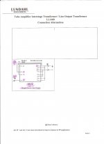
Attached schematic how I wired the Lundhals LL1660, help will welcome?
I don't know if it matters, but I think you have the outputs the wrong way round on the LL1660. Plus should go to plus.
Have you got a 150v glow tube e.g. 0D3 from B+ to ground? As in my schematic? If you do and you have the DN2540 set for 32.5 to 35mA, then the 0D3 should light up pink and you can only have 150v on the top of the LL1660 and 145v on the plate. Follow the schematic and the voltages should be correct!
Your wiring diagram for the LL1660 is fine - doesn't really matter that the output is reversed or not. If you have wired the LL1660 as in your schematic it will be correct.
I asked Thomas Mayer aka Vinylsavor about Lundhals wiring, attached the correct wiring for next diyers.
So all measurements were taken with swapped the polarity at the output😱
Attachments
It doesnt matter. The thing is that your 26 preamp is an anode follower, and anode followers inverts the signal. That means that what is going out from your anode is an inverted signal from that of your source. As long as you do the same on both channels, there is no difference for the measures or the following amplifier.
If your scope has two channels you can put a sine on the input and measure input and output signals simultaneus. If the two sines has their tops on the same vertical line, your output is the same polarity as your signal. But, as I said, it really doesnt matter.
If your scope has two channels you can put a sine on the input and measure input and output signals simultaneus. If the two sines has their tops on the same vertical line, your output is the same polarity as your signal. But, as I said, it really doesnt matter.
Last edited:
I dont know. Depends on how Per Lundahl chosed to draw his spec. But you dont have to care fortunately😉
Hi Felipe,
as I wrote you can connect the secondary either way depending if you want the stage to be inverting or non inverting. Some transformers have different high frequency performance depending on the polarity. Not the Lundahls. So you can choose.
Best regards
Thomas
as I wrote you can connect the secondary either way depending if you want the stage to be inverting or non inverting. Some transformers have different high frequency performance depending on the polarity. Not the Lundahls. So you can choose.
Best regards
Thomas
- Home
- Amplifiers
- Tubes / Valves
- #26 pre amp