Do you have any test equipment besides a multimeter? Do you have any CD or other source for sine test tones? What are the rail voltages, with no music playing?
rail voltage was normal at 33V + and - with respect to ground ... there was no DC at output ... and also there are turn on and off transients ... BTW this amp is only mono amp and i am currently using it to power my subwoofer just found that it lacking in bass compared with my LM1875 ...
and sorry i just have a multimeter only ... 😀 ... i dun have much to spend on test equipment and test CD ...
hi dannyjmf
I have 2 sets of LM3875TF amplifier, 2 sets of LM3886TF amp, 3 sets of LM1875T amp, 4 sets of difference style of PSU for chip-amp,
2 sets of 12AU7 tube buffer for chip-amp and 1 set of OP-amp pretone and buffer for chip-amp.
And I have 3 pairs of branded minicombo loudspeakers, 1 pair of bookshelf branded and 1 pair of DIY speaker.
I never heard the more treble sound from LM3875 chip-amp even during run-in period.
IMO there will be something wrong with your components, mainly your diy speakers.
Good Luck
Tommy55
Hi Dannyjmf
Sorry, I just saw you want to built mono amp for sub-woofer.
There are many schematics for using chip-amp and op-amp for this purposed.
It will better to search for the right thing you need.
Bye
Tommy55
Sorry, I just saw you want to built mono amp for sub-woofer.
There are many schematics for using chip-amp and op-amp for this purposed.
It will better to search for the right thing you need.
Bye
Tommy55
There are a few things that you can do to your amp that will improve it. My immediate guess for why it is sounding bright and bass light would be that it is a characteristic of the power supply caps. 33V is a good easy voltage for the 3875 and 4700uF is fine as a value. But the reservoir caps always have a direct effect on the overall sound. What you are hearing can also be a common characteristic of new reservoir caps so it can be worth giving them a bit of a blast to get the chemistry changing. Otherwise a change of brand might be your answer (and you don't need to go to the exotica either.
I would be careful about putting even 10pF in the feedback loop. These amps aren't unity gain stable and even though they look like op amps, they aren't really. But a filter in front of the amp would definitely be a good idea. At about 70kHz or so with just a cap to ground after the input R. An nF or two, or whatever the figure is with your R. Change this with impunity or depending on what values you have to hand. This won't change the in-band response, but may improve the general 'quality' as you don't pass the amp too much rf and less of what it can't manage. Another marginal improvement that may help is to have a 47uF electrolytic between the rails and ground at the amp. Again this value isn't important and you can go up to whatever value you like. Something small there is also a possibility, though these can introduce brand new oscillations. Finally an output L//R will definitely help. 2uH or thereabouts (15 or 20 turns in two layers on a 6mmm drill bit) in parallel with anything from 10 ohms downwards. Again no change to the actual response but an easier load for the amp and less rf coming back in from the speaker cables. Incidentally, with smaller values of R, 3R3 or 2R2, you can get away with 400mW resistors, even though they are in series with the output.
Somewhere among these things, assuming your layout isn't truly botched, you should discover an amp that sounds remarkably good.
Last edited:
ChristianThomas,
Wow, you actually hit on basically ALL of the right places to look! Impressive.
I will have to add some points, about the VALUES of the decoupling and reservoir capacitances. I will post the basic results, here, and will then post the derivation in the next post, so people won't necessarily feel that they have to wade through all of it.
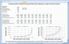
Attached is an image of an Excel spreadsheet that implements equations (5a) and (6a) below, with plots of the calculated upper and lower bounds of the reservoir capacitance vs Max Rated Output Power.
Actually, the value of the small electrolytic decoupling cap which should be placed right at the chipamp might matter, for the transient response. There is a minimum acceptable value, based on the amplifier's specs.
The minimum required C and the maximum tolerable L for the decoupling capacitance, and its maximum tolerable connection lengths, CAN be calculated, such that it can support the maximum slew rate and the rail voltage and ripple specs of the chipamp, for a maximum excursion of the output or power supply input current in the minimum time.
For the 19V/us LM3886, I once calculated something like 200 uF minimum, but the inductance requirement was such that it could only be met by using three 68 uF caps in parallel, less than an inch from each power pin. I thought that was very intertesting. But it WAS for a 15%-higher rail voltage. See
http://www.diyaudio.com/forums/powe...lm-caps-electrolytic-caps-23.html#post2806854
for the very first of that type of derivation that I attempted. (I can send or post a list of the rest of the links to the related material that I have posted, if you're interested.)
---
Similarly, the 4700uF cap's minimum required value can be easily calculated.
For the original related derivation, see:
http://www.diyaudio.com/forums/chip...-rms-power-5-watt-chip-amp-5.html#post3309631
For the exact derivation, see my next post.
Note that the main equations have been verified to be accurate, using multiple detailed LT-Spice simulations. So unless I have made some trivial algebra errors, the ones presented below should be accurate, as well.
Estimated Power Supply Reservoir Capacitance Needed for Worst-Case Signal, at Max Rated Output Power:
With Δt:
(1a) C_upper_bound ≥ ((Vpeak_max / Rload) ∙ Δt ) / (Vrail_unloaded - Vclip - Vpeak_max - (ESR ∙ Vpeak_max / Rload))
(2a) C_lower_bound ≥ ((Vrms_max / Rload) ∙ Δt ) / (Vrail_unloaded - Vclip - (√(2) ∙ Vrms_max) - ( ESR ∙ Vrms_max / Rload ))
With fmains instead of Δt:
(3a) Cupper_bound ≥ ( 1 /( 2 ∙ fmains )) ∙ (Vpeak_max / Rload) / (Vrail_unloaded - Vclip - Vpeak_max - ( ESR ∙ Vpeak_max / Rload ))
(4a) Clower_bound ≥ ( 1 /( 2 ∙ fmains )) ∙ irms_max / (Δv - ( ESR ∙ irms_max ))
With an approximation for ESR (ESR eliminated), i.e. ESR = 0.02/(C ∙ Vrating): (approximation, for electrolytic capacitors ONLY!)
(5a) Cupper_bound ≥ ( (Vpeak_max / Rload) / (Vrail_unloaded - Vclip - Vpeak_max) ) ∙ ( ( 1 / fmains ) + ( 0.02 / cap_Vrating )) )
(6a) Clower_bound ≥ ( (Vrms_max / Rload) / (Vrail_unloaded - Vclip - (√(2) ∙ Vrms_max)) ) ∙ ( ( 1 / fmains ) + ( 0.02 / cap_Vrating ))
where
cap_Vrating = Max DC Voltage Rating of capacitor(s)
Vpeak_max is the maximum peak of the output voltage when the amp is producing its max rated output power,
Vrail_unloaded is the peak rail voltage when no input signal is present,
Vclip is the voltage between the power rail (AT the amplifier device) and the amplifier output, which for the LM3875 is given in a plot of Vclip vs Rail Voltage, in the datasheet. (For a 33-Volt rail, Vclip is 4.5 Volts, for a typical LM3875.) In a typical discrete transistor amplifier, Vclip would be the minimum Vce voltage plus the voltage across the usually-small series resistor.
And Δv_max is the worst-case peak-to-peak ripple voltage, which makes the minima of the rail voltage during production of max rated output power = Vrail_unloaded - Δv_max.
As we know, the signal voltage across the load, in series with the voltage across the amplifier itself, can only occupy the voltage space between the load ground (or downsteam connection) and the minima of the p-p ripple voltage.
If the reservoir capacitance is not sufficient, and the ripple voltage minima descend into the space occupied by the voltage across the amplifier, then ripple-shaped chunks will be gouged out of the output signal voltage!
PROCEDURE:
Calculate C values using (5a) and (6a), first, then find ESRs at 2*fmains frequency, as if using standard cap values that result in total capacitances that are above the calculated values, and then use (3a) and (4a) with the actual published ESRs that were found, to calculate more-accurate minimum-required C values.
It is recommended that at least 25% be added to the indicated capacitance values, to account for transformer regulation and variations in AC Mains voltage.
Wow, you actually hit on basically ALL of the right places to look! Impressive.
I will have to add some points, about the VALUES of the decoupling and reservoir capacitances. I will post the basic results, here, and will then post the derivation in the next post, so people won't necessarily feel that they have to wade through all of it.
Attached is an image of an Excel spreadsheet that implements equations (5a) and (6a) below, with plots of the calculated upper and lower bounds of the reservoir capacitance vs Max Rated Output Power.
Actually, the value of the small electrolytic decoupling cap which should be placed right at the chipamp might matter, for the transient response. There is a minimum acceptable value, based on the amplifier's specs.
The minimum required C and the maximum tolerable L for the decoupling capacitance, and its maximum tolerable connection lengths, CAN be calculated, such that it can support the maximum slew rate and the rail voltage and ripple specs of the chipamp, for a maximum excursion of the output or power supply input current in the minimum time.
For the 19V/us LM3886, I once calculated something like 200 uF minimum, but the inductance requirement was such that it could only be met by using three 68 uF caps in parallel, less than an inch from each power pin. I thought that was very intertesting. But it WAS for a 15%-higher rail voltage. See
http://www.diyaudio.com/forums/powe...lm-caps-electrolytic-caps-23.html#post2806854
for the very first of that type of derivation that I attempted. (I can send or post a list of the rest of the links to the related material that I have posted, if you're interested.)
---
Similarly, the 4700uF cap's minimum required value can be easily calculated.
For the original related derivation, see:
http://www.diyaudio.com/forums/chip...-rms-power-5-watt-chip-amp-5.html#post3309631
For the exact derivation, see my next post.
Note that the main equations have been verified to be accurate, using multiple detailed LT-Spice simulations. So unless I have made some trivial algebra errors, the ones presented below should be accurate, as well.
Estimated Power Supply Reservoir Capacitance Needed for Worst-Case Signal, at Max Rated Output Power:
With Δt:
(1a) C_upper_bound ≥ ((Vpeak_max / Rload) ∙ Δt ) / (Vrail_unloaded - Vclip - Vpeak_max - (ESR ∙ Vpeak_max / Rload))
(2a) C_lower_bound ≥ ((Vrms_max / Rload) ∙ Δt ) / (Vrail_unloaded - Vclip - (√(2) ∙ Vrms_max) - ( ESR ∙ Vrms_max / Rload ))
With fmains instead of Δt:
(3a) Cupper_bound ≥ ( 1 /( 2 ∙ fmains )) ∙ (Vpeak_max / Rload) / (Vrail_unloaded - Vclip - Vpeak_max - ( ESR ∙ Vpeak_max / Rload ))
(4a) Clower_bound ≥ ( 1 /( 2 ∙ fmains )) ∙ irms_max / (Δv - ( ESR ∙ irms_max ))
With an approximation for ESR (ESR eliminated), i.e. ESR = 0.02/(C ∙ Vrating): (approximation, for electrolytic capacitors ONLY!)
(5a) Cupper_bound ≥ ( (Vpeak_max / Rload) / (Vrail_unloaded - Vclip - Vpeak_max) ) ∙ ( ( 1 / fmains ) + ( 0.02 / cap_Vrating )) )
(6a) Clower_bound ≥ ( (Vrms_max / Rload) / (Vrail_unloaded - Vclip - (√(2) ∙ Vrms_max)) ) ∙ ( ( 1 / fmains ) + ( 0.02 / cap_Vrating ))
where
cap_Vrating = Max DC Voltage Rating of capacitor(s)
Vpeak_max is the maximum peak of the output voltage when the amp is producing its max rated output power,
Vrail_unloaded is the peak rail voltage when no input signal is present,
Vclip is the voltage between the power rail (AT the amplifier device) and the amplifier output, which for the LM3875 is given in a plot of Vclip vs Rail Voltage, in the datasheet. (For a 33-Volt rail, Vclip is 4.5 Volts, for a typical LM3875.) In a typical discrete transistor amplifier, Vclip would be the minimum Vce voltage plus the voltage across the usually-small series resistor.
And Δv_max is the worst-case peak-to-peak ripple voltage, which makes the minima of the rail voltage during production of max rated output power = Vrail_unloaded - Δv_max.
As we know, the signal voltage across the load, in series with the voltage across the amplifier itself, can only occupy the voltage space between the load ground (or downsteam connection) and the minima of the p-p ripple voltage.
If the reservoir capacitance is not sufficient, and the ripple voltage minima descend into the space occupied by the voltage across the amplifier, then ripple-shaped chunks will be gouged out of the output signal voltage!
PROCEDURE:
Calculate C values using (5a) and (6a), first, then find ESRs at 2*fmains frequency, as if using standard cap values that result in total capacitances that are above the calculated values, and then use (3a) and (4a) with the actual published ESRs that were found, to calculate more-accurate minimum-required C values.
It is recommended that at least 25% be added to the indicated capacitance values, to account for transformer regulation and variations in AC Mains voltage.
Attachments
Last edited:
DERIVATION OF EQUATIONS FOR MY PREVIOUS POST.
YOU CAN PROBABLY SKIP THIS UNLESS YOU'RE INTERESTED.
The power supply reservoir capacitance's minimum required value can be easily calculated:
Many people use the same approximate equation, based on the maximum RMS sine current at the rated output power. But that is only valid for higher-frequency sines (i.e. frequency much greater than mains frequency), and assumes that the ripple is very small, and does not account for the worst-case situation. This equation gives a lower bound estimate for the required capacitance. The RMS-based equation is:
(1) C_lower_bound ≥ ( irms_max ∙ Δt ) / (Δv - ( ESR ∙ irms_max ))
We could also use an equation derived by assuming a low-frequency sinusoidal load current. For a reasonably-low frequency, say 20 Hz, such an equation should give a higher estimate than the one based on RMS current. But a single sine is also not the worst case input signal, in terms of current demand, except in the limit as its frequency approaches zero.
The true worst-case uses the same equation form as the RMS sine case, but it uses the peak value instead of the RMS value, where the peak value is the maximum amplitude of the sine at the rated max output power.
(2) C_upper_bound ≥ (ipeak_max ∙ Δt ) / (Δv - (ESR∙ipeak_max))
which gives C as the capacitance that will allow only up to some desired maximum rail-voltage dip of Δv Volts to occur, when a specified maximum rated peak current, ipeak_max, is pulled out of the capacitance for a specified time Δt.
In this case, for a full wave bridge rectifier, we would use the time between charging pulses as Δt, i.e. Δt = 1/(2 fmains), where fmains is the AC mains frequency (i.e. 50 Hz or 60 Hz), giving:
Capacitance Needed for Worst-Case Signal, at Max Rated Power:
(3) Cupper_bound ≥ ( 1 /( 2 ∙ fmains )) ∙ ipeak_max / (Δv - ( ESR ∙ ipeak_max ))
(4) Clower_bound ≥ ( 1 /( 2 ∙ fmains )) ∙ irms_max / (Δv - ( ESR ∙ irms_max ))
Or, using an approximation (at least at first to avoid having to iterate as much to find a reasonable ESR value), i.e. ESR = 0.02/(C ∙ Vrating):
(5) Cupper_bound ≥ ( ipeak_max / Δv ) ∙ ( ( 1 / fmains ) + ( 0.02 / cap_Vrating )) (approximation, for electrolytic capacitors ONLY)
(6) Clower_bound ≥ ( irms_max / Δv ) ∙ ( ( 1 / fmains ) + ( 0.02 / cap_Vrating )) (approximation, for electrolytic capacitors ONLY)
where cap_Vrating = Max DC Voltage Rating of capacitor.
NOTE that equations (2), (3), and (5) were tested with detailed LT-Spice simulations and have been found to be accurate. Therefore it is assumed that equations (1), (4), and (6) are accurate, as well. Assuming that all of the subsequent algebra was done correctly, that means that equations (1a) through (6a), at the end, should also accurate. But, as always, the user must perform their own due diligence, and verify that their results are accurate.
NOTE that if the ESR is not MUCH lower than the desired (Δv / ipeak_max) or (Δv / irms_max), which are the maximum IMPEDANCES that we want the load to see, in each case, then the minimum required capacitance value would be excessive, as the denominator of (3) "blows up". In that case, either relax the Δv requirement OR use multiple parallel smaller-value caps, to lower the overall ESR, which would become ESR(ncaps) = (ESR of one cap) / ncaps.
Aside: For calculating decoupling cap values, for a worst-case transient with a change of di Amps in a small-valued Δt seconds, use (1) and (2) above, but replace the i..._max variables with di.
We still need some way to calculate or constrain or eliminate Δv:
We know that the peak output voltage must never cause the amplifier to clip, which means:
(7) Vpeak_max <= Vrail_unloaded - Vclip - Δv_max
(8) Δv_max <= Vrail_unloaded - Vclip - Vpeak_max
(9) Δv_max <= Vrail_unloaded - Vclip - √(2) ∙ Vrms_max
where
Vpeak_max is the maximum peak of the output voltage when the amp is producing its max rated output power,
Vrail_unloaded is the peak rail voltage when no input signal is present,
Vclip is the voltage between the power rail (AT the amplifier device) and the amplifier output, which for the LM3875 is given in a plot of Vclip vs Rail Voltage, in the datasheet. (For a 33-Volt rail, Vclip is 4.5 Volts, for a typical LM3875.) In a typical discrete transistor amplifier, Vclip would be the minimum Vce voltage plus the voltage across the usually-small series resistor.
And Δv_max is the worst-case peak-to-peak ripple voltage, which makes the minima of the rail voltage during production of max rated output power = Vrail_unloaded - Δv_max.
As we can now see, the signal voltage across the load, in series with the voltage across the amplifier itself, can only occupy the voltage space between the load ground (or downsteam connection) and the minima of the p-p ripple voltage.
If the reservoir capacitance is not sufficient, and the ripple voltage minima descend into the space occupied by the voltage across the amplifier, then ripple-shaped chunks will be gouged out of the output signal voltage!
Since Vrail_unloaded and Vclip can be asumed to be fixed values, Vpeak_max and Δv_max have a dependent relationship, i.e. either one will determine the other's value.
For this example, we must have Δv_max <= 28.5 - Vpeak_max .
In case we need them, there are also some simple relationships between the Vpeak_max maximum rated output voltage and the max rated output current and power:
ipeak_max = Vpeak_max / Rload
Vpeak_max = √( 2 ∙ Prms_max_rated ∙ Rload)
Ipeak_max = √( 2 ∙ Prms_max_rated / Rload)
irms_max = Vrms_max / Rload
Vrms_max = √( Prms_max_rated ∙ Rload)
Irms_max = √( Prms_max_rated / Rload)
If we replace all of the Δv and i..._max variables with expressions in terms of V..._max (and Vrail_unloaded and Vclip), in the equations for C, above, then we should find that attempting to specify a peak output voltage that is too high, i.e. too close to the rail voltage, will result in an excessively-large or infinite capacitance value, from the equations.
Estimated Power Supply Reservoir Capacitance Needed for Worst-Case Signal, at Max Rated Output Power:
With Δt:
(1a) C_upper_bound ≥ ((Vpeak_max / Rload) ∙ Δt ) / (Vrail_unloaded - Vclip - Vpeak_max - (ESR ∙ Vpeak_max / Rload))
(2a) C_lower_bound ≥ ((Vrms_max / Rload) ∙ Δt ) / (Vrail_unloaded - Vclip - (√(2) ∙ Vrms_max) - ( ESR ∙ Vrms_max / Rload ))
With fmains instead of Δt:
(3a) Cupper_bound ≥ ( 1 /( 2 ∙ fmains )) ∙ (Vpeak_max / Rload) / (Vrail_unloaded - Vclip - Vpeak_max - ( ESR ∙ Vpeak_max / Rload ))
(4a) Clower_bound ≥ ( 1 /( 2 ∙ fmains )) ∙ irms_max / (Δv - ( ESR ∙ irms_max ))
With an approximation for ESR (ESR eliminated), i.e. ESR = 0.02/(C ∙ Vrating): (approximation, for electrolytic capacitors ONLY!)
(5a) Cupper_bound ≥ ( (Vpeak_max / Rload) / (Vrail_unloaded - Vclip - Vpeak_max) ) ∙ ( ( 1 / fmains ) + ( 0.02 / cap_Vrating )) )
(6a) Clower_bound ≥ ( (Vrms_max / Rload) / (Vrail_unloaded - Vclip - (√(2) ∙ Vrms_max)) ) ∙ ( ( 1 / fmains ) + ( 0.02 / cap_Vrating ))
where cap_Vrating = Max DC Voltage Rating of capacitor(s).
PROCEDURE:
Calculate C values using (5a) and (6a), first, then find ESRs at 2*fmains frequency, as if using standard cap values that result in total capacitances that are above the calculated values, and then use (3a) and (4a) with the actual published ESRs that were found, to calculate more-accurate minimum-required C values.
It is recommended that at least 25% be added to the indicated capacitance values, to account for transformer regulation and variations in AC Mains voltage.
How should it look like according to you then? 😕Maybe I am wrong but that LM3875 looks weird to me!. Can it be a "fake" IC?😕
CORRECTION!
I forgot to do the substitutions in equation (4a), in both posts above, to put Ipeak_max and Δv in terms of Vpeak_max.
I posted:
(4a) Clower_bound ≥ ( 1 /( 2 ∙ fmains )) ∙ irms_max / (Δv - ( ESR ∙ irms_max ))
It should be:
(4a) Clower_bound ≥ ( 1 /( 2 ∙ fmains )) ∙ (Vpeak_max / Rload) / (Vrail_unloaded - Vclip - Vpeak_max - ( ESR ∙ (Vpeak_max / Rload) ))
The picture you can see is a CAD drawing showing the "TF" package, all insulated. There is also a non-insulated version called "T" and this is what you see here.Compare to photo from datasheet?
There are a few things that you can do to your amp that will improve it... an output L//R will definitely help. 2uH or thereabouts (15 or 20 turns in two layers on a 6mmm drill bit) in parallel with anything from 10 ohms downwards. Again no change to the actual response but an easier load for the amp and less rf coming back in from the speaker cables. Incidentally, with smaller values of R, 3R3 or 2R2, you can get away with 400mW resistors, even though they are in series with the output...
Christian, I wonder if you could elucidate for a total imbecile: I'm having similar issues with my PD 3875 build incuding a fairly 'edgy' top end. Do you mean something like this?
What do you mean by "15 or 20 turns in two layers on a 6mmm drill bit"?
Cheers,
DaveB.
Attachments
Yup, that's exactly the circuit.
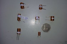
I mean 10 turns on each layer and you wind them by hand on a drill bit. After 10 turns you come back on yourself - still winding in the same direction and then you get both connections at the same end. They look jolly cute, incidentally - I'll see if I can find a pic to upload. Use 0.8mm or 1mm wire, or more, not so much for resistance but because it's less springy and will hold its position better.
I mean 10 turns on each layer and you wind them by hand on a drill bit. After 10 turns you come back on yourself - still winding in the same direction and then you get both connections at the same end. They look jolly cute, incidentally - I'll see if I can find a pic to upload. Use 0.8mm or 1mm wire, or more, not so much for resistance but because it's less springy and will hold its position better.
Here we go. It seems from reading the values marked that 20 turns will give you a bit more than 2uH, but I think you'll have to count the turns - I don't remember what I did. One or two of those have 3 or 4 layers - and you can tell by which ends the leads are at.
Edit, maybe not wrong. 10 turns on each layer is probably about right.
Edit, maybe not wrong. 10 turns on each layer is probably about right.
Attachments
Last edited:
Yup, that's exactly the circuit.
Good man, thanks for that. I finished the amp (my first) three evenings ago and in many respects I'm very happy with it, not least sitting with a beer listening to something I made. But the lack of bottom end and the abrasive top mean that I suppose I've a way to go yet, though to be fair the ProAcs are pretty unforgiving. Onwards...
Cheers,
DaveB.
...immediate guess for why it is sounding bright and bass light would be that it is a characteristic of the power supply caps. 33V is a good easy voltage for the 3875 and 4700uF is fine as a value.
Actually Christian, while you're here... 🙂
The Peter Daniels kit has 1500uf per rail per chip on the amp board, close to the chip, and nothing at all on the PSU but the diodes. Would you recommend:
an additional 4700uf per rail on the PSU (or more), in addition to the caps on the amp (I've got 25V DC per rail after the rectifier)?
what do you think about the 'snubber' option?
which caps would you recommend (I'm in the frankly far too cold for far too long UK)?
I know this has been gone over and over before but your opinion would be really appreciated; this is a great forum.
Cheers,
DaveB.
Actually Christian, while you're here... 🙂
The Peter Daniels kit has 1500uf per rail per chip on the amp board, close to the chip, and nothing at all on the PSU but the diodes. Would you recommend:
an additional 4700uf per rail on the PSU (or more), in addition to the caps on the amp (I've got 25V DC per rail after the rectifier)?
what do you think about the 'snubber' option?
which caps would you recommend
Yes I would! You could happily go to 10,000uF if you wanted, too. I don't believe 1500uF is enough; though I believe the original Gaincard only used 1000uF.
If by snubber you mean putting a small R between the two caps then I would say probably not. Between two sets of proper reservoir capacitors then possibly yes, as there is an argument for it behaving as a big filter. But my instinct is to have what's on the reservoir caps immediately available and not affected by an additional time constant.
As for brands there must be hundreds of recommendations here. Personally I don't usually go for exotica brands and tend to choose by looking for specs that show they weren't designed 25 years ago. Rubycon are almost always technologically good, BC components too. You can go for the BHCs but you will get a slightly Naimy sound whether you want it or not. Also my experience is that they can be quite bass light. I don't know if LesW is just BHC or Kendiel but if he has a third choice then that may be worth going with.
Incidentally, you can probably raise those rail voltages in due course, though 50V is probably plenty. Just to mention that you do have room - though it may not be the most important thing.
- Status
- Not open for further replies.
- Home
- Amplifiers
- Chip Amps
- LM3875 gainclone too much treble