I'd lengthen the potshaft instead, much easyer. I have 6 mm alutubes that I use, but a wooden flowerpin works if you have some sturdy glue armored with whatever you can find.
Depens how hard the aluminium is. But I believe it should be possible. Perhaps you could try on a different piece of aluminium first.I have wood drill like you suggested but for aluminum do you believe can works?
Ofcourse! Duh! Why did I not think of that. That is a good option.I'd lengthen the potshaft instead, much easyer.
Front panel
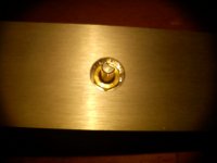
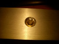
If I understand you correctly....take of the Front Panel........Drill the appropriate hole in the Chassis to mount the POT........then Drill a much Larger hole in the Front Panel (just slightly larger than the Nut holding the Pot)...... replace the Front Panel... and with the right sized Knob it should cover the hole
If I understand you correctly....take of the Front Panel........Drill the appropriate hole in the Chassis to mount the POT........then Drill a much Larger hole in the Front Panel (just slightly larger than the Nut holding the Pot)...... replace the Front Panel... and with the right sized Knob it should cover the hole
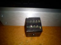
I need to reduce the fron plate to install the pot, who knows how I can do it?

I normally do this in wood. So I dont drill a pilot hole where the shaft goes through. Otherwise the wood drill doesnt center well. I the drill a large hole for the pot only from the insde out.
But in this case drilling a hole large enough for the mounting nut from the front a better idea if the shaft is long enough
But in this case drilling a hole large enough for the mounting nut from the front a better idea if the shaft is long enough
Yes my chassis front plate have 10mm is too broad/widht and can't fix the pot.
Hello Felipe,
I had the same predicament with my Gold Point attenuator. I took mine to a machine shop and have it tapped (M10 x 0.75) from the inside all the way to the front so that I have the full lenght of the shaft on the front side.
Or have it "counter bore" 5mm from the inside is another option too. This way, the plate holds the pot not the chassis as it will be a pain to install another bracket on the chassis from my layout.
Abe
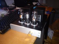
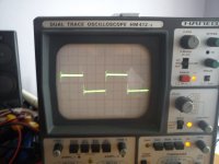
Looks good. Are you going to run any measurements on it? Noise, thd, square waves, stuff like that?
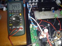
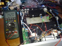
Tomorrow will solder the pot & connect the CCS + VR150 and do the measurements, I'm tired now is time to relax, good night.
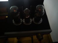
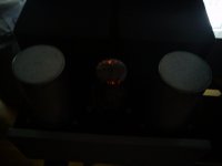
Finished work
Cool! How do you like the sound?
I have a Type 76( with Cathode follower buffer), and a Type 6SN7 transformer coupled preamp here and I am comparing my type 26 to it.
The 26 of course is still new, so I will give it some time before making my final assessment. But alas, I have to be away for business for two weeks.
Abe
Last edited:
Tomorrow will solder the pot & connect the CCS + VR150 and do the measurements, I'm tired now is time to relax, good night.
Ooops, I posted too early. I thought when you say 'Finished Work" it means it is now singing in your music room 😀.
Will wait for your impression.
Abe
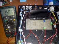
Pics just for fun, one measuring voltage across 100R to adjust CCS mA, voltage plate both tubes, square wave both tubes.🙂
Attachments

- Home
- Amplifiers
- Tubes / Valves
- #26 pre amp