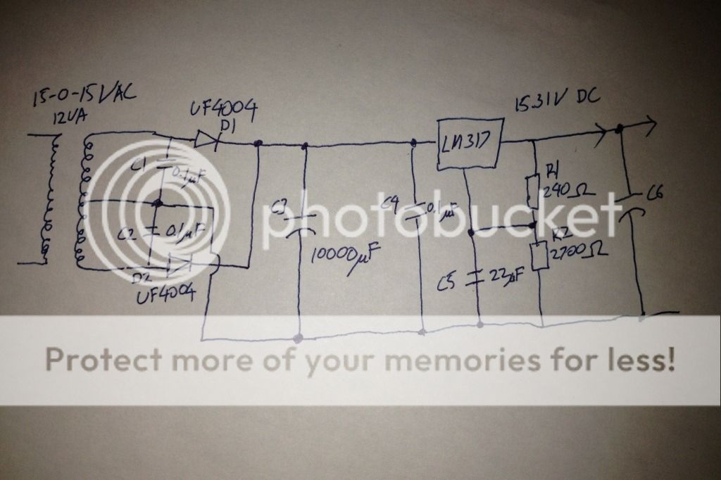
Put a 3.3 ohm 3 watt (or greater) resistor between C3 and C4. Add another capacitor equal to C3 across C4. This will drop the ripple into your regulator from 1 volt to .1 volts or a 20 db improvement. That is the most bang for the buck you will get.
Use 10 uf as the output capacitor. It needs to be very close to the actual regulator output pin. More is not going to do much. Less is not enough.
A 12 VA transformer will limit you to a around .565 Amps out.
Use 10 uf as the output capacitor. It needs to be very close to the actual regulator output pin. More is not going to do much. Less is not enough.
A 12 VA transformer will limit you to a around .565 Amps out.
Put a 3.3 ohm 3 watt (or greater) resistor between C3 and C4. Add another capacitor equal to C3 across C4. This will drop the ripple into your regulator from 1 volt to .1 volts or a 20 db improvement. That is the most bang for the buck you will get.
Use 10 uf as the output capacitor. It needs to be very close to the actual regulator output pin. More is not going to do much. Less is not enough.
A 12 VA transformer will limit you to a around .565 Amps out.
Please pardon me, how did you get 0.565 Amps? 😀
Please pardon me, how did you get 0.565 Amps? 😀
A 15 volt 12VA transformer will produce 1.414 x 15 volts. 1.414 x 15 x .565 = 11.98
Simon,
that calculation allows for 11.98W of output from a 12VA transformer.
That does not make any allowance for the manufacturer's de-rating when the transformer feeds a capacitor input filter.
This de-rating factor (DF) is usually ~0.7.
i.e. the maximum continuous DC power output is ~70% of the VA rating. 12VA gives ~8.4W. @ the rectifier that equates to Idcmax = 8.4/15/sqrt(2) = 0.396Adc
The easy way to get to this answer is to use:
Idc continuous ~= 50% of Iac rating. (Iac = 12VA / 15Vac = 0.8Aac)
The reason that the DF is required is to prevent overheating of the transformer as a result of the short duration, but high value, of currents passing around the primary and secondary circuits. These high currents create more heat due to I^2R losses.
The transformer VA rating is determined by the manufacturer assuming that the transformer is driving a resistive load.
It's when you ask the transformer to drive something other than a resistive load, that the user MUST understand that the manufacturer's standard rating no longer applies !!!!!!!!!!!!
Mains electricity is not safe. You must properly research your project to maintain sufficient safety.
It's when you ask the transformer to drive something other than a resistive load, that the user MUST understand that the manufacturer's standard rating no longer applies !!!!!!!!!!!!
Mains electricity is not safe. You must properly research your project to maintain sufficient safety.
Last edited:
For an 800mA transformer, I think AndrewT's 396mA is a little too low and Simon's 565mA is a little too high, using the typical current derating of 0.62.
It depends very much on the transformer type, and size of the filter cap: a good toroidal in association with an overlarge cap can result in power factors significantly worse than 0.5.For an 800mA transformer, I think AndrewT's 396mA is a little too low and Simon's 565mA is a little too high, using the typical current derating of 0.62.
Opinion on which derating factor must be applied varies, but all agree there is an important derating to be considered.
Now another factor must be considered: it also affects (a lot) PSU *regulation* (DC drop from no or light load to full load).
In the 70's, when I was a beginner, I used to have long heated discussions with my (excellent quality) custom transformer winder.
I bitterly complained about the 15% to 20% DC voltage loss in power amp rails I measured when fully driven, but he tested the transformers in the test bench, under full load, at his well equipped factory, and showed me it was no more than 5%.
Of course, the 5% he measured before my very eyes, was with a resistive load.
At that time, I just factored that loss into the design and let it be.
Later I understood that, like explained in an earlier post, current charging a capacitor is made out of low duty cycle bursts, and remembering loss is I squared x R , it's clear that, say, passing 2A during 50 milliseconds is far worse than passing 1A during 100 milliseconds, although *average* current for both is the same.
Live and learn. 🙂
For the two diode rectifiers as you showed the VA rating to tectified draw is x .9 to 1.0. For a full wave rectifier it is 1/2 of that.
Since you have more voltage than you need the primary issue is transformer heating. With closer voltage margins then droop under load can be an issue.
Since you have more voltage than you need the primary issue is transformer heating. With closer voltage margins then droop under load can be an issue.
Thanks guys for the info. 🙂
It sounds like I need a larger transformer. I have a 24VA 12V transformer that I initially intend to use, but I'll have to forgo the 2 stage regulation.
It's a USB SPDIF device. I am targeting at 12V 500-1000mA. It probably doesn't need that much current or ultra low noise performance, but I don't mind a bit more flexibility should I decide to use it for something else in the future.
It sounds like I need a larger transformer. I have a 24VA 12V transformer that I initially intend to use, but I'll have to forgo the 2 stage regulation.
Navy, what is the regulator supposed to feed? Line stage?
It's a USB SPDIF device. I am targeting at 12V 500-1000mA. It probably doesn't need that much current or ultra low noise performance, but I don't mind a bit more flexibility should I decide to use it for something else in the future.
Not larger but higher voltage.
For single stage regulation (and you don't need more, *at all*), you need 15/16V AC to have a raw voltage around 20/21V and be certain that the regulator will have ample margin to work.
For single stage regulation (and you don't need more, *at all*), you need 15/16V AC to have a raw voltage around 20/21V and be certain that the regulator will have ample margin to work.
Not larger but higher voltage.
For single stage regulation (and you don't need more, *at all*), you need 15/16V AC to have a raw voltage around 20/21V and be certain that the regulator will have ample margin to work.
For single stage regulation, I can use the 24VA 0-12V traffo.
For 2 stage regulation, my 15-0-15V is only 12VA. It can probably do fine for my current use, but I'd prefer it to be able to output more current should I need it for something else in the future.
Well, if you already know the answer, why bother asking?
By the way, the
And the
By the way, the
is not up to the task with24VA 0-12V traffo.
loads.1000mA.
And the
will burst in flames if you even *try*.15-0-15V , only 12VA
I have a feeling that we are not in the same page. 😀
I'm beginning to think so 😀
That's simple arithmetics: assuming the sinewave is not distorted under load (optimistic), the peak nominal voltage would be 12√2=16.97V.For single stage regulation, I can use the 24VA 0-12V traffo.
Give 2V for the bridge rectifier, that leaves you with 15V.
A standard regulator needs ~2V to operate, thus it looks just sufficient.... except the DC will have ripple, and there is no margin for mains variations.
In practice the sinewave will be distorted (the tops will be flattened), there will be a finite ripple, even with a large cap, and you should allow for a 10~15% drop in the mains voltage.
To use your 12V transformer, you would need a schottky bridge, a big filter cap and a LDO regulator.
It is perhaps simpler to opt for a slightly higher voltage.
To use your 12V transformer, you would need a schottky bridge, a big filter cap and a LDO regulator.
It is perhaps simpler to opt for a slightly higher voltage.
Or, am I better off with something like this:

Would the 24VA 0-12V be able to squeeze out 1A?
Or else, I'd just go with an LM317 (Motorola) followed by MC7812 (On). From datasheet, the MC7812 has better noise spec (120uV vs 360uV @12V), but worse ripple rejection.
Either way, I am returning that small transformer.
- Status
- Not open for further replies.
- Home
- Amplifiers
- Power Supplies
- LM78xx output decoupling capacitor
