The version where the speaker chambers are tilted 90 degrees so they are vertical instead of horizontal, resulting in a taller and narrower box - does it affect sound or anything?
Is it ok to use a 1/2" roundover bit on the inside/outside of the ports and edges of the box in addition to the speaker holes? or should they have a smaller radius curve..
Obviously it has a huge negative impact on sound quality and especially stereo imaging. But if it's the only way to fit your requirements for space then it's far better than the alternative, ie. not building one at all.
If you can manage it. Use the recommended epoxy glues, and better still, have made interlocking cabinet edge. Then I highly recommend using a 1/2" round over tool everywhere. But it basically means that you can't use screws anywhere which makes the construction more tricky. But ultimately also more rigid and durable.
Does it has to be this particular cap?Changing the input cap to a 470nF WIMA cap (part no. MKS0C034700E00) which fits in the original hole pitch of 2.54mm (1/10") will both improve sound quality and completely eliminate power-on pops.
I've already ordered these caps https://www.elfa.se/elfa3~se_sv/elfa/init.do?init=2&shop=ELFA_SE-SV&item=67-256-51&
Does it has to be this particular cap?
It's the one that I use so I know it works perfectly well. Also better than "ultra hi-end audio grade" Jensen paper-in-snake-oil ones.
The WIMA is also the only polyester/polypropylene cap (that I know of) that fits in the 2.54mm pitch.
Last edited:
Ok, then I'll hope that my "not even a trail of snake oil" caps, aluminum electrolyte, will work fine as well 😉It's the one that I use so I know it works perfectly well. Also better than "ultra hi-end audio grade" Jensen paper-in-snake-oil ones.
1st photos of my build - Baffles
Hi
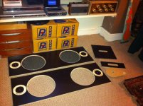
I thought I'd post a photo of my build so far.....
Have routed holes for the HP10W's and rounded off with 6mm roundover bit... Routed the insets for the PHT-407N's so they fit flush, awaiting delivery of hole saws to finish off. I have cut the port slots with a 30mm flat wood borer and joined the holes up to form a slot with a jigsaw. I still have to glue them all together, sand and finish off with the roundover bit......
To the right of the photo you can see the circle cutter jig that I made for the hole cutting and the inset routing for the tweeters.
I shall be ordering the PHT-407N's next week and start gluing up the speaker grills and drivers to the baffle. As far as I can tell, I wont need to make any mods to the tweeters like the piezos? I shall of course use sealant when I mount them to make sure they are airtight.......
Hi
I thought I'd post a photo of my build so far.....
Have routed holes for the HP10W's and rounded off with 6mm roundover bit... Routed the insets for the PHT-407N's so they fit flush, awaiting delivery of hole saws to finish off. I have cut the port slots with a 30mm flat wood borer and joined the holes up to form a slot with a jigsaw. I still have to glue them all together, sand and finish off with the roundover bit......
To the right of the photo you can see the circle cutter jig that I made for the hole cutting and the inset routing for the tweeters.
I shall be ordering the PHT-407N's next week and start gluing up the speaker grills and drivers to the baffle. As far as I can tell, I wont need to make any mods to the tweeters like the piezos? I shall of course use sealant when I mount them to make sure they are airtight.......
Attachments
battery charge meter
Hi
I'm a bit of an old skool analog lover so I'd like a little nod to that in my boominator.... I'm thinking of fitting this battery charge indicator (without wiring the backlight to save power)
Universal Battery Charge Indicator | eBay
but I'm wondering if it would be a drain on the battery compared to a little colour changing led indicator, anybody enlighten me on this?
BJ
So I can have a short vent as long as I keep an eye on the port air velocity so it doesnt exceed the "chuffing speed" for the choosen diameter of the port. OK sounds good to me.In principle, no.
On the Boominator however that implies you're making the reflex port smaller which in turn will increase air speed in the reflex port, so here, yes, it will bring a fair bit of problems.
If you're just making it shorter without decreasing the area then you're making the tuning frequency and Qs much higher which brings many other problems.
In both cases, a basic understanding of how a reflex cabinet works will help you realize what problems and how they can be overcome, so I suggest you search the internet for some information on this, if you want a more thorough explanation.
I just have a some questions left, then ill leave you alone Saturnus 😛
1. If my cone excursion doesn't exceed Xmax, do I still need a highpass filter? If yes, which capacitator and resistance would you use for a vented box with Fb=70Hz and F3=64Hz.
2. You keep mentioning the Q of the box. The only Qbox I can find is a formula for calculating an appropiate Vb for a closed enclosure. The formula for calculating an appropiate Vb for a vented enclosure is:
Vb = 15*Vas*(Qts^2,87). So what's the Qbox for a vented design?
And trust me, I've searched the internet for answers to avoid going onto peoples nerves, but can't find the answers for these questions. So it would be kind of you if you could answer these questions
/André
Last edited:
Hi
I'm a bit of an old skool analog lover so I'd like a little nod to that in my boominator.... I'm thinking of fitting this battery charge indicator (without wiring the backlight to save power)
Universal Battery Charge Indicator | eBay
but I'm wondering if it would be a drain on the battery compared to a little colour changing led indicator, anybody enlighten me on this?
BJ
Personally I think that is rather dull looking gauge. It's cheap though.
Search google, amazon, or fleabay for "voltmeter gauge" for a vast selection
Power consumption will typically be 100mA with the backlight, and 10 to 1000 times less without it. It entirely depends on construction. 100-200uA seems to be typical without backlighting though. That's 0.0012-0.0024W at 12V.
Battery charge indicator
Thanks Saturnus
I agree that the battery charge meter I used as an example is a bit boring, I didn't think to search for "voltmeter", there are a lot more choices under that heading. So it seems that it wont be too much of a drain on my battery, that settles it, I shall be fitting one.....
This afternoon I have been gluing together the port/handle assembly, Tomorrow, when the epoxy is fully set, I shall be tidying up the ports with a file, finishing off with sandpaper and routing the edges of the port hole with my roundover bit......
every week gets a little closer to finishing......
BJ
I might go the whole hog and fit an analogue vu meter too...
Panel VU Meter TR-35 0dB=1.288V 35x35mm LED | eBay
BJ
Panel VU Meter TR-35 0dB=1.288V 35x35mm LED | eBay
BJ
I am going to use small bolts plus silicone sealant to secure the drivers/grills to the baffle and epoxy to glue them to the center brace. My question is will epoxy itself hold the foam/grill/baffle together without the bolts if I use a good amount? I ask because I made 2 of the speaker holes like 1-2 mm too big which is not a lot and dry fitting was fine, just a tiny tiny overhang from the speaker foam. If I decide to not use bolts will the epoxy hold and will that foam stick to the driver? Those bolt holes are pretty close to that routed edge in any case! Most likely using bolts + silicone.
It really takes a good read in this thread to realize that the design is optimized in so many ways.
Reading from beginning to end I've collected a good portion of notes!
Cannot add much more than I'm looking forward for more talks on the Qubinator (suiting my needs the best)!
Cheers & shoutouts to all ppl how have REPEATEDLY answered infinity times the same questions...
Reading from beginning to end I've collected a good portion of notes!
Cannot add much more than I'm looking forward for more talks on the Qubinator (suiting my needs the best)!
Cheers & shoutouts to all ppl how have REPEATEDLY answered infinity times the same questions...
My question is will epoxy itself hold the foam/grill/baffle together without the bolts if I use a good amount?
It will be difficult as epoxy is too liquid for this use unless you use a filler.
Don't ever used silicone in a closed compartment - it outgasses acetic acid when it cures. It attacks other metals, it attacks certain plastics, and it prevents epoxy from curing. Basically, don't use it to build a boominator. I learned this lesson the hard way when I sealed an outdoor electrical enclosure with silicon - it burnt out in spectacular fashion less than a year later, and the copper was horribly corroded.
I also wouldn't use epoxy because it's hard when it's cured. Vibrations from playing music, impacts, people sitting on it, thermal expansion, etc. might cause the epoxy to eventually fail.
Use urethane. I built my box using Loctite "PL Premium" adhesive. It doesn't outgas anything too horrible when it cures, and it's somewhat flexible when it's cured.
Don't ever used silicone in a closed compartment - it outgasses acetic acid when it cures. It attacks other metals, it attacks certain plastics, and it prevents epoxy from curing. Basically, don't use it to build a boominator. I learned this lesson the hard way when I sealed an outdoor electrical enclosure with silicon - it burnt out in spectacular fashion less than a year later, and the copper was horribly corroded.
It's been stressed several times that the silicone must be solvent-free.
Epoxy will work but I recommend silicone between woofer and baffle.
Does it matter if the handle port is higher or lower on the sides or is it best dead center?
What size resistors for ksn-1001a originals? paired w goldwoods.
And why change input/feedback caps?
I have a question. I live in California, where did you buy ksn-1001a originals? and what kind of resistors are you getting? I know that Saturnus recommended 33 ohm's but do you know what's the wattage? Are you getting 10W as (Leggler) used on page 3551, because I have 33 ohm 1/2W resistor and it looks small compared to (Leggler) picture on page 3551.
Thanks.
He probably got them directly from the current manufacturers webshop.
Piezo Source, Inc.
Resistors can be 1, 2, or 3W. Depends on what you can find. With a TA2020 or similar amp, only 1W is absolutely needed.
They do have one requirement though. They must not be wire-wound. That means you cannot use regular ceramic power resistor but use metal film or better yet, carbon composition. I vastly prefer the carbon composition ones as they distort and float in value which would normally disqualify them from any build but those effects seems to work tremendously well with piezo tweeters and make them sound less piezo'ie.
Thank you for your quick response!
I just ordered the Piezo's and the resistors (those were the last two things that I needed).
I can't wait to start building it!
Thanks again.
I just ordered the Piezo's and the resistors (those were the last two things that I needed).
I can't wait to start building it!
Thanks again.
Hi, I'm looking for an alternative replacement of the PHT-407N, as the sources I've found does not ship to Sweden.
I found this one that seems to feature a very similar frequency response curve (I add this as the "recommended 5000hz 12db/oct" crossover point does not seem necessary to the boominator application given its power.
Diskanthorn
Any comments ?
I found this one that seems to feature a very similar frequency response curve (I add this as the "recommended 5000hz 12db/oct" crossover point does not seem necessary to the boominator application given its power.
Diskanthorn
Any comments ?
- Home
- Amplifiers
- Class D
- The Boominator - another stab at the ultimate party machine