Hi everybody!
I'm repairing an old Lab Power Supply right now. It used to have some weird current sourcing/sinking used in the power supply. I already completely "modernized" the control circuit using JFET current sources etc. so my design only needs +/-15V supply. But i want to keep the original transformer that puts out a single 50V supply. So my question is: what is the best solution to convert 50V to +/-15V? I already thought of two zeners and a resistor, two cascaded 7815 (altough there would be a problem of too high input voltage) or regulation to 30V and using a rail splitter… What do you think is the best? Or is there something better?
Thanks in advance!
How much current is needed for that +/-15V? Does the transformer has an 50Vac output or those 50V are after rectifyer and filter cap?
50V after filter cap. The +/-15V rails have to supply power to four opamps (TL074) so i think no more than 100mA are needed.
Ok then, you can go either with a floating ground or with voltage doubler, witch one seams more to your liking?
similar discussions here:
http://www.diyaudio.com/forums/power-supplies/219974-how-split-single-40v-into-15v-2.html
and here:
http://www.diyaudio.com/forums/power-supplies/229503-15vdc-7815-7915-power-supply.html
doubler is technically O.K. and probably best, but since you already have a high voltage it doesn't seem reasonable to go to 100v first ...
QUAD used a capacitive splitter w/o doubler in their 606 amp to obtain +/-V and virtual gnd from single DC
— Why not buy Keith Snook a BEER —
note T15 / T16 device to keep balance
I read those threads but thats not exactly what i'm searching for. The problem that bugs me most is the quite high voltage from the transformer. If i had a 15 to 20V winding, i would just use the voltage doubler design seen everywhere. But 50V is too high for feeding 78XX regulators. So i dont think a voltage doubler would make sense in this case. I think the most desireable solution is to use two 15V zeners and a resistor? What do you think?
A dual-output capacitive supply with 15V zeners seems like the most reasonable solution.
That won't waste too much power.
That won't waste too much power.
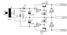
I am not a verry big fan of the virtual ground ideea, it might create problems when connected to other fix grounded circuits... i think voltage doubler would be better, 50Vdc means about 35Vac from the power transformer, and with voltage doubler about +/-50Vdc, a zenner diode each rail helped by a BJT would do just nicely.
I am not a verry big fan of the virtual ground ideea, it might create problems when connected to other fix grounded circuits...
Why?
He has a transformer in there...
Its still floating isnt it?
That is just a voltage doubler, and what i have sugested...
PS: What use do you have for R1 and C1?
PS: What use do you have for R1 and C1?
One easy solution would be a simple DC-DC converter designed for telecom use. They're 48 Vdc in and you can choose the desired output voltages. They usually will tolerate 36-72 volts on the input.
It would become a voltage doubler if it happened to be operated open circuit, which is normally never the case.That is just a voltage doubler, and what i have sugested...
PS: What use do you have for R1 and C1?
R1 limits current spikes, at power on for instance, and C1 sets the average output current. Each cycle, it transfers a charge of C1*2*Vpeak to one of the outputs, leading to an average current of Q*Fmains, 50Hz in this case.
- Status
- Not open for further replies.
- Home
- Amplifiers
- Power Supplies
- 50V to +/-15 - Best solution?