Well, I never though of it that way. Just do the best you can to get matched compliments. Try for better than 5%.... I probably built mine with 1-2%. -Richard
BTW - I rarely hear any mention anywhere on DIYAUDIO forums -- the music. So here is a recommendation to listen to: Got to HD-Tracks and down load a tune called Freight Train Jam. Its from an album called The World is a Ghetto by WAR. Deep, deep bass, transients, highs and great playing.
I use flac format. Enjoy! -Richard
Last edited:
How would this amp do with a .7VRMS DA converter instead of a 2VRMS one into a pair of 600-650 Senn's or a Hifimann HE-500?
thanks,
dennis h
thanks,
dennis h
You may not be able to bleed your ears 😉
jan
Thanks Jan, will be ordering volume 3 shortly...
dennis h
BJT Compliment mathing jig circuit -
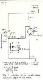
Here is a matching jig for BJT typs. Adjust values for your needs. Use +/- 12vdc for matching compliments. I published this in 1982 to go along with a MC pre-preamp article of mine. A sensitive DMM current range can be used in place of 'meter' shown. At null the two are matched.
Thx-RNMarsh
Here is a matching jig for BJT typs. Adjust values for your needs. Use +/- 12vdc for matching compliments. I published this in 1982 to go along with a MC pre-preamp article of mine. A sensitive DMM current range can be used in place of 'meter' shown. At null the two are matched.
Thx-RNMarsh
Attachments
Last edited:
I now have a full parts kit, and pwb thanks to Jack.
Just ordered vol 3 to get the article, but until I get it, I was wondering what voltage PS I need?
I am going to use a couple of Salas shunt boards as the regs, the group buy is closing in a few days.
Randy
Just ordered vol 3 to get the article, but until I get it, I was wondering what voltage PS I need?
I am going to use a couple of Salas shunt boards as the regs, the group buy is closing in a few days.
Randy
Just ordered vol 3 to get the article, but until I get it, I was wondering what voltage PS I need?
+-12V.
Here is a matching jig for BJT typs. Adjust values for your needs. Use +/- 12vdc for matching compliments. I published this in 1982 to go along with a MC pre-preamp article of mine. A sensitive DMM current range can be used in place of 'meter' shown. At null the two are matched.
Thx-RNMarsh
Finally, a use for box of Keithley meters I've been collecting since the 1960s!
Finally, a use for box of Keithley meters I've been collecting since the 1960s!
speaking of which, I have recently some issue with mine, can i drop u a PM?
And got my transistors set today 🙂
Marsh headphone amp PCB
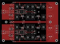
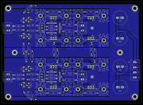
I have been working on producing a double sided pcb for the project, which includes mounted heatsinks. I tried to make it reasonably compact, so the width of the board would fit the 100mm eurocard standard, which makes it adaptable to a lot of enclosures (such as Hammond, Box enclosures, etc.).
I think the layout is pretty much optimized now, but comments are welcome before I send it to manufacture.
Top and bottom layers are attached below.
Attachments
Last edited:
One thing which Dick did was include ceramic decoupling caps on the electrolytics. He also mentioned trimming the value of R10 via potentiometer:
http://www.diyaudio.com/forums/head...eadphone-amp-linear-audio-55.html#post3340912
http://www.diyaudio.com/forums/head...eadphone-amp-linear-audio-55.html#post3340912
I doubt any differences could be heard, particularly with Class A output bias, but I don't like several layout choices,
why the large +.- supply trace loop areas - think about the current loop paths, reducing their area
I don't like close spaced plane fill - adds fringing C to traces, I prefer explicit gnd return design, hierarchy of clean/dirty, start on star - planes can be fine for the low level signal gnd - the interface to power gnds should be controlled by layout
I disagreed with Marsh earlier in the thread on his weighting of high frequency effects - but hybrid gnd techniques can cover both my audio/power current path concerns and higher frequency too - but you need to design for it (smt caps are really handy)
system options also can impact layout - what PS, case gnding, external signal entry and signal gnd, any provision for RF filtering on I/O
and are you planing on 4-wire termination of the headphone or more common TRS
Are tech specs (real, no simulation) of this amp available somewhere?
Something like:
min/max power supply voltage
power consumption idle/full load
input/output impedance
max input/output voltage
unity gain stable?
snr, thd, dynamic range, imd, crosstalk
slew rate
frequency response
dc offset
..
(without special tweaking)
Btw, can linear audio be ordered as pdf download?
I think that the heat sinks for the board you propose are over-sized. With +/- 12V rails each output device is going to dissipate less than a watt assuming a worst case load impedance of 30 ohms. In the boards I built (and despite the protestations of Mr. Marsh) I affixed the output and driver transistors to the bottom of the chassis. I also found that a piece of aluminum flashing was sufficient for heat sinking.
I've been using mine to drive Sennheiser HD-650's which aren't as difficult a load as Grado's.
If I were doing new boards I would allow for surface mount input devices like the MMBF5460/5457, and while you're at it, probably smt versions of the 5088/87's.
I've been using mine to drive Sennheiser HD-650's which aren't as difficult a load as Grado's.
If I were doing new boards I would allow for surface mount input devices like the MMBF5460/5457, and while you're at it, probably smt versions of the 5088/87's.
Thanks jackinnj and jcx for your comments.
Regarding bypass capacitors (I think Marsh mentionned film caps), I omitted them due to concerns about hf resonance, but I may include pads anyway to give the choice to the user. Also missing is the big electrolytic cap across the power rails as suggested in the article, which I may also include in the final layout.
For R10 trimming, I thought to place a trim-pot during testing, and replace it with a fixed value resistor when lowest distortion has been set.
jcx, I guess it is always a compromise between different parameters. The goal was to keep power lines as far as possible from input signal and feedback line, while providing a clean return current at the center of each half of the board. It helps also making the signal traces short, in particular reducing feedback loop length.
I will try to reduce the power rails loop area. One way to do that would be to adopt a wide board shape rather than narrow, but I think the improvement will be limited. Another way would be to place the power connections nearer the center of the board, I am going to try that.
Theoretically, a better way would be to run + and - close together, but when I tried it, it resulted with power lines crossing signal line, and signal path going through unnecesarry contortions. Finally, it loses the advantages of having the rails running almost always close to power ground, except when combining power and signal ground into one.
I prefer power rails encircling the enemy in plain sight like the old days, rather than quiet commando-style infiltration.
Regarding capacitance of two ground planes, I will widen the gap between the two planes, or follow your suggestion of "composite" ground with signal-ground plane/ power star ground.
Small heat sinks are all that will be needed.
I dont like smd of any kind unless they are transistors of exceptional charactereistics which cannot be found in any other package. I also tend to put IC/transistor sockets everywhere, for future changes, experimenting and the like. Cant do that with smt. But thats just me... -Richard
I dont like smd of any kind unless they are transistors of exceptional charactereistics which cannot be found in any other package. I also tend to put IC/transistor sockets everywhere, for future changes, experimenting and the like. Cant do that with smt. But thats just me... -Richard
Heatsinks are intended to be used with higher bias if needed by adding another diode in series (which I will add to the board, instead of air-wiring two diodes on D2)
For general chassis layout:
Chassis double-insulated from main earth, PSU reg and amp board close to each other. Star ground point connection on PSU side. External input signal socket insulated from chassis, cable outer shield connected to chassis (by small plug near rca), chassis connected to star , signal ground connected to star.
Output connection: running the 4 wires from the output connectors of the pcb to external xlr-4 socket, rather than TRS to minimize crosstalk.
For filtering, a small film cap (around 220pF) will be added on the pcb input
- Home
- Amplifiers
- Headphone Systems
- Marsh headphone amp from Linear Audio