Got it. Thanks diyhk!
Where can I find a schematic or BOM?
TIA
Giulio
Isn't shown in the first page?
Hi
U1 : "150Mbps 4/0 channel Isolator (TI ISO7640FM or equivalent)"
- Does ISO7240M fits ?
U3 : "1Mbps 3/0 or 4/0 channel Isolator (TI ISO7230/ISO7240 or equivalent)"
- Does ISO7240M fits ? (ISO7240C = TTL)
Regards
Phil
U1 : "150Mbps 4/0 channel Isolator (TI ISO7640FM or equivalent)"
- Does ISO7240M fits ?
U3 : "1Mbps 3/0 or 4/0 channel Isolator (TI ISO7230/ISO7240 or equivalent)"
- Does ISO7240M fits ? (ISO7240C = TTL)
Regards
Phil
Isn't shown in the first page?
Silly me,
I opened the picture and overlooked the text above.
Thanks!
giulio
Hi, I just send you the paypal fee to get two of these amanero isolator bare pcbs.
Best
Jean Claude
Best
Jean Claude
The postmans dog ate it....
No, The postman say..Sir! finally the package was found and will be send tomorrow on Feb 21... Thanks God and post office in Taiwan !! 😀
No, The postman say..Sir! finally the package was found and will be send tomorrow on Feb 21... Thanks God and post office in Taiwan !! 😀
Nice to hear that.
Congrats~
populating the board
I have the isolator in hand and would like to know the orientation of the texas isolator before soldering.
I only using it as isolator between the amanero combo converter and the BII dac
Please see the attached
1)Is the isolator orientation correct ?
2) The arrows point to the isolated BC ( bit clock )output?
3) The corresponding pin on the left side of the image corresspond to the BC input ?
4) Where to apply the dc voltage in ?
thanks
kp93300
Attachments
No, The postman say..Sir! finally the package was found and will be send tomorrow on Feb 21... Thanks God and post office in Taiwan !! 😀
🙂
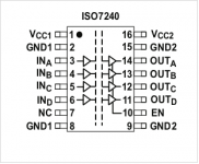
iso7240mdw pin out
The attached is the pin out assignment for the isolator
I have a few questions :
Vcc1 and GND 1 correspond to power supply input between 3.3 v to 5 v dc ?
VCC2 and GND 2 also need dc power between 3.3 v to 5 V ?
INa in correspond to OUT a?
INa , IN b, IN c and IN d pin corresponds to input i2s signals of MCLK, FSCLK, CLK AND DATA ?
thanks and apologies for simple questions
kp93300
Attachments
- Home
- Vendor's Bazaar
- diyinhk Store