Yes - at least make it a DHT headphone amp, otherwise you'll get anything.
DHT headphone amp
+1🙂
hi guys
let's say i intend to parallel feed the output stage and ultrapath as well.
we know the capacitor should go to the output tube's cathode but in the case of using filament bias, where should the capacitor go to?
if it's ac filament, i'll have a hum bucking pot and will wire to pot's wiper.
any suggestions?
thx!
bg
Here is my suggestion: biased from regulated power supply through cathode follower, no caps.
http://www.diyaudio.com/forums/tubes-valves/183329-one-more-4p1l-se-8.html#post2567581
You can get up to 5W of clean power from a couple of tubes.

http://www.diyaudio.com/forums/tubes-valves/183329-one-more-4p1l-se-8.html#post2567581
You can get up to 5W of clean power from a couple of tubes.
I finally had a chance to get back to my map and now have it running in pentode mode for the input stage, triode for the output. Battery bias on both.
It seems to work well and sounds pretty clean. There is a lot of clean up to do, but it's a nice start so far. The loose layout is causing some oscillations for time to time, and one of the valves is fairly microphonic. All things that can be fixed I think.
It seems to work well and sounds pretty clean. There is a lot of clean up to do, but it's a nice start so far. The loose layout is causing some oscillations for time to time, and one of the valves is fairly microphonic. All things that can be fixed I think.
Hi Juan!hi guys
let's say i intend to parallel feed the output stage and ultrapath as well.
bg
There is no idea in using parallel feed and ultrapath at the same time. Or one could say that in case of parallel feed the ultrapath cap should go from cathode to ground. That would be the same position as a normal bypass cap.
Also; it is not a good idea to combine filament bias with ultrapath, as the hole idea of filament bias is to get rid of the cathode bypass cap. And the ultrapath cap is a special case cathode bypass. With filament bias the cathode resistor becomes so small, that it doesn´t need bypass.
It might be a good idea to combine filament bias and parallel feed.
Good luck!
Thorsten Larsen
To bump this back up - I've now gone to a 6sN7GT on the input and am happy with it. It sounds good and has enough gain to fully drive the 4P1L outputs and is quiet. It's a very smooth sound, probably a lot of H2, but not too sweet. Will check tomorrow.
Running the 6SN7 with LED bias (2X red LED) 125V on the plate, about 5mA current.
Running the 6SN7 with LED bias (2X red LED) 125V on the plate, about 5mA current.
I was wondering about driving PSE 4P1L with 2C22, pretty much half a 6SN7. I'm wondering if it would work in two stages if I had 2v coming out of my DAC, like an ODAC for instance. I have Mark Audio Alpair 10s. It would be marginal. Right now I get about 0.5v from my DAC with 3 stages, 26>4P1L>4P1L.
I'm using 7193 with gyrator Mu-follower load and led bias to drive a 45SE. I have an ODAC and also using the 26 preamp. Bear in mind that the 45SE is really remanding and that for the 4P1L PSE you will be fine with 70Vpp - need to check load line when get back home. The 7193 is at full tilt about 8mA but is cap coupled. Why not an 6e5p or 6j11p shunt cascode?
Andy I'm not getting a lot of gain out of the 6SN7, but enough. I see about 3.2V RMS from the 4P1L/OPT secondary with 1.5V RMS into the 6SN7. I think I'll have more gain if the 6SN7 is run off a CCS.
The main thing is to have enough negative bias at the 4P1L grid so that it doesn't clip first.
It seems that with my -17.5V battery bias (2 old 9V in series) the output is limited. I may go back to 2x 9V + 2X 1.5V to see what happens. Could be that it's simply hitting the B+ limit.
The main thing is to have enough negative bias at the 4P1L grid so that it doesn't clip first.
It seems that with my -17.5V battery bias (2 old 9V in series) the output is limited. I may go back to 2x 9V + 2X 1.5V to see what happens. Could be that it's simply hitting the B+ limit.
Here you go Andy. You can get in theory up to 2W with 40Vpp drive when biasing the pair at full tilt = 250V, 80mA. Just a reference:
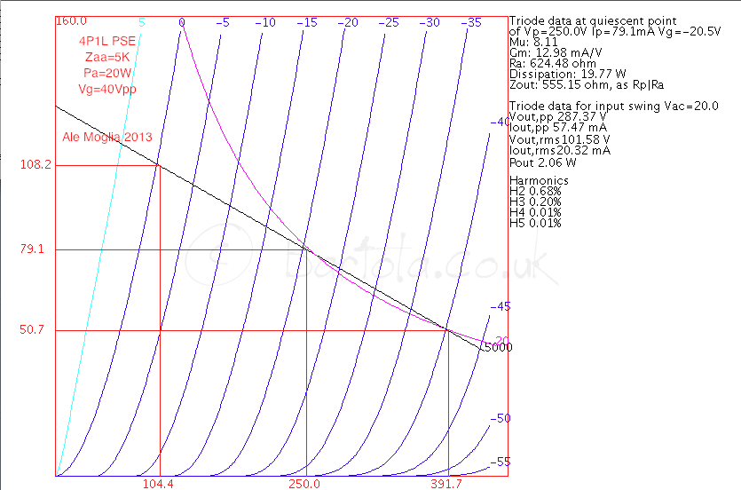
Ale
Ale
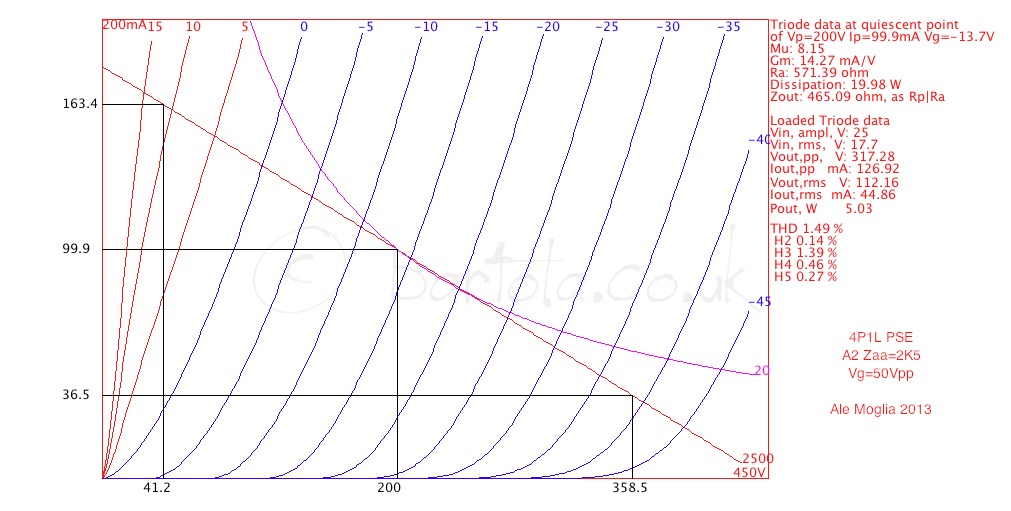
Try 2K4 load, and up to +12V drive. 5W output from a paralleled pair.
Also, try to apply constant positive voltage on G3, you may need less positive swing in A2.
Also, try to apply constant positive voltage on G3, you may need less positive swing in A2.
What are you thinking for voltage on G3?
I am talking, to get curves when some positive voltage, like +12V, is applied to G3, instead of connecting it to anode or to ground. Triode curves of pentodes shift such a way to the left, closer to the Y - axis.
I can redo the A2 swing loadline yes. For positive G3 bias I need to trace curves again, may be in the future as am not with a lot of time at the moment unfortunately 🙁
Ale
Ale
I was wondering about driving PSE 4P1L with 2C22, pretty much half a 6SN7. I'm wondering if it would work in two stages if I had 2v coming out of my DAC, like an ODAC for instance. I have Mark Audio Alpair 10s. It would be marginal. Right now I get about 0.5v from my DAC with 3 stages, 26>4P1L>4P1L.
Why don't you use an ECC40? You would get 2W out, as shown by Ale, with 0.5V rms in.
You can use the ECC40 both for min. THD and tune it for H2 cancellation being the main component of the spectrum.
There you have a two-stages PSE with 5 valves only....
Last edited:
I have an amp with a ECC40 input. I can see your point about the gain, but I prefer DHTs. I suppose I should look at a 2-stage amp. It certainly makes sense, but the only tube I know that sounds remotely like a DHT is the 2E22, and I'm not sure about that either. I do transformer couple, so one thing I should look at is sneaking in a 2x step-up somewhere. I suspect the likely place for more gain is in the DAC stage somewhere. I'm only inputting 0.5v to my preamp, and it can't be hard to improve on that!
Hi Anatoliy,
I think I got it right here reflecting your experiments. Yes, 5W in A2 with 2k5 load with only 50Vpp:
Cheers,
Ale
I think I got it right here reflecting your experiments. Yes, 5W in A2 with 2k5 load with only 50Vpp:
Cheers,
Ale
Thank you Ale!
In my experiment I had about 220V on anode, so at clipping level of H2 was slightly less, level of H3 was slightly high, so dynamic distortions caused by "rectification" of an envelope were slightly lower. However, in the original schematic negative supply for cathode follower need to have more voltage, because despite of almost cut-off of output tube on clipping hard clipping of the current source was still audible.
In my experiment I had about 220V on anode, so at clipping level of H2 was slightly less, level of H3 was slightly high, so dynamic distortions caused by "rectification" of an envelope were slightly lower. However, in the original schematic negative supply for cathode follower need to have more voltage, because despite of almost cut-off of output tube on clipping hard clipping of the current source was still audible.
Why don't you use an ECC40? You would get 2W out, as shown by Ale, with 0.5V rms in.
You can use the ECC40 both for min. THD and tune it for H2 cancellation being the main component of the spectrum.
There you have a two-stages PSE with 5 valves only....
ECC40 direct coupled to 4P1L looks promising.
Question for 45 and Andy.
Do you have practical experience with smaller B+ on ECC40, say 130V/6mA op.point.
Also, if there is any difference in sound quality between Long glass Miniwatt ECC40 and Short glass Tungsram ECC40?
Tnx.
- Home
- Amplifiers
- Tubes / Valves
- One more 4P1L SE