EDIT: First pictures up on page 4, along with a change in some components
So I don't know if this is the right spot, apologize if it isn't. A couple times a year my friends and I take a trip to his hunting camp (we don't hunt) and there is no power except for gasoline generators. Usually this results in one or a few of us running our car batteries dead playing music over the course of the May 24 weekend. So I decided to build a system to take with me to run off battery.
Goals
107+db output
40 Hour Uninterrupted playback with reserve to also power an MP3 player
Fit in my car for transport
Under $200(CDN) (not counting enclosure)
Sound quality better than the iPod docks etc. that my friends usually bring, which are tinny and don't disperse far.
Background - I mostly browse Diyma since I spend most of my time on my car. I currently have a Car PC setup with (G530, Win 8, SSD, Delta 1010LT) - Mimo 720S - Iogear Wireless KB - ID XS28, Scan 18w/4434G00 (Active) - IDMax 12D4v3 IB - PPI P900.4 - Kenwood XR4S
It runs full active with 64 band parametric EQ per channel, and also was tuned with a calibrated EMM-6.
First off, I am not expecting SQ anywhere near my home, car, or recording setup.
The parts I purchased, taking into account price first, efficiency second, SQ third.
MCM Audio Select 10'' Die Cast Woofer with Paper Cone and Cloth Surround - 100W RMS 8ohm | 55-2961 (552961) | MCM Audio Select
3.5mm one way xmax, 96db (across the usage range, -3 is like 90hz, that's fine for this)
MCM Audio Select Piezo Horn Tweeter | 53-800 (53800) | MCM Audio Select
95db, easily replaceable if they are completely useless ($5 total)
http://www.ebay.ca/itm/230608705311?ssPageName=STRK:MEWNX:IT&_trksid=p3984.m1497.l2649#ht_3790wt_906
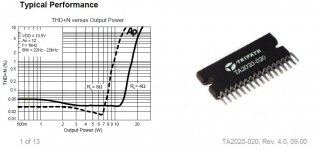
Basic tripath, with some decent components
Special Price 10W 12V Module Polycrystalline Solar Panel-in Solar Cells, Solar Panel from Electrical Equipment & Supplies on Aliexpress.com
10W, fits the dimensions of the top of the box perfectly
http://1000bulbs.com/pdf/ubD5745-spec.pdf
18aH should be good for 40+ hours while powering an iPod with the solar panel getting 2-3 sunshine hours a day
WinISD says approx 110-112db peak at 1m with 15w rms input. This is with 0.66cu ft per driver and tuned to 72.89hz.
I am going to slightly modify this value however and run 0.8cu ft per driver which nets me (compared to 0.66) -0.2db 100-200hz, +1 db 70-125hz tuned to 73hz.
Sketchup so far for 0.6 cu ft, which I will change Box 0.6cu ft Dual 10 by wy2sl0 - 3D Warehouse
I designed the battery/amp compartment into the rear 1/4 of the box along the entire width.
Any comments would be grateful. I just ordered this week so I am thinking this should be done in a month or so, and start getting parts in the next 3 weeks.
So I don't know if this is the right spot, apologize if it isn't. A couple times a year my friends and I take a trip to his hunting camp (we don't hunt) and there is no power except for gasoline generators. Usually this results in one or a few of us running our car batteries dead playing music over the course of the May 24 weekend. So I decided to build a system to take with me to run off battery.
Goals
107+db output
40 Hour Uninterrupted playback with reserve to also power an MP3 player
Fit in my car for transport
Under $200(CDN) (not counting enclosure)
Sound quality better than the iPod docks etc. that my friends usually bring, which are tinny and don't disperse far.
Background - I mostly browse Diyma since I spend most of my time on my car. I currently have a Car PC setup with (G530, Win 8, SSD, Delta 1010LT) - Mimo 720S - Iogear Wireless KB - ID XS28, Scan 18w/4434G00 (Active) - IDMax 12D4v3 IB - PPI P900.4 - Kenwood XR4S
It runs full active with 64 band parametric EQ per channel, and also was tuned with a calibrated EMM-6.
First off, I am not expecting SQ anywhere near my home, car, or recording setup.
The parts I purchased, taking into account price first, efficiency second, SQ third.
MCM Audio Select 10'' Die Cast Woofer with Paper Cone and Cloth Surround - 100W RMS 8ohm | 55-2961 (552961) | MCM Audio Select
3.5mm one way xmax, 96db (across the usage range, -3 is like 90hz, that's fine for this)
MCM Audio Select Piezo Horn Tweeter | 53-800 (53800) | MCM Audio Select
95db, easily replaceable if they are completely useless ($5 total)
http://www.ebay.ca/itm/230608705311?ssPageName=STRK:MEWNX:IT&_trksid=p3984.m1497.l2649#ht_3790wt_906
Basic tripath, with some decent components
Special Price 10W 12V Module Polycrystalline Solar Panel-in Solar Cells, Solar Panel from Electrical Equipment & Supplies on Aliexpress.com
10W, fits the dimensions of the top of the box perfectly
http://1000bulbs.com/pdf/ubD5745-spec.pdf
18aH should be good for 40+ hours while powering an iPod with the solar panel getting 2-3 sunshine hours a day
WinISD says approx 110-112db peak at 1m with 15w rms input. This is with 0.66cu ft per driver and tuned to 72.89hz.
I am going to slightly modify this value however and run 0.8cu ft per driver which nets me (compared to 0.66) -0.2db 100-200hz, +1 db 70-125hz tuned to 73hz.
Sketchup so far for 0.6 cu ft, which I will change Box 0.6cu ft Dual 10 by wy2sl0 - 3D Warehouse
I designed the battery/amp compartment into the rear 1/4 of the box along the entire width.
Any comments would be grateful. I just ordered this week so I am thinking this should be done in a month or so, and start getting parts in the next 3 weeks.
Last edited:
Running the tweeter and woofer together will net approx a 4 ohm load, and will output 15 or so watts per channel. Even at 8w RMS that is only a 3db decrease which is above my 107db requirement 🙂
Thanks, I will post pictures.
Thanks, I will post pictures.
Running the tweeter and woofer together will net approx a 4 ohm load, ...
No. It doesn't work like that.
No. It doesn't work like that.
Goes to show you what I know. I have used actives as long as I can remember, I have never even made a passive!
Glad I read up. Ok well -3 db is ok, as I said. If it ends up NOT being, I will buy another TA to run each set of drivers seperately. I am thinking it should be ok, it is not like I am trying to run at concert levels. 😀
I will probably run the 10 up to about 2.5-3k and then cut them. I have more reading to do about piezo wiring, although I see their impedance graph sort of works as an automatic lf attenuator.
Hi,
The 8 ohm drivers will extend battery life over 4 ohm drivers,
at maximum volume. Read up on piezo's, they don't work
like normal tweeters, e.g. you use series caps for attenuation
and series R for response shaping, just doing it right will make
a big difference to the apparent treble quality you end up with.
rgds, sreten.
I read up on them, thanks. I will be using an 8 ohm resistor across the leads, and HP them at 3khz, LP on woofer the same.
Believe it or not this took me hours of changing different designs and dimensions to make sure everything fit, in a box as SMALL as possible and getting flat response (from the enclosure).
Here is my final design
Tripath Boom Box by wy2sl0 - 3D Warehouse
Believe it or not this took me hours of changing different designs and dimensions to make sure everything fit, in a box as SMALL as possible and getting flat response (from the enclosure).
Here is my final design
Tripath Boom Box by wy2sl0 - 3D Warehouse
You've basically just copied my Boominator design. That's fine. You have however forgotten the very basics of the design.
You can't use 12mm plywood for a cabinet design like yours. There´s far from sufficient bracing to prevent a serious amount of loss in the bass region due to cabinet vibrations. You need to go at least 15mm (18mm baffle) to compensate.
The Boominator works so well because it's bipolar. Your design will sound very thin in comparison unless you bafflestep it by dampening above about 382Hz with a -6dB bafflestep filter.
Should also note that the Boominator is only 40% bigger but houses 4x 10" drivers. Which makes a huge difference.
Last edited:
You needn't do that 🙂I will be using an 8 ohm resistor across the leads, and HP them at 3khz,
Piezos crossover at around 3.5KHz (depending on model) all by themselves.
Just curious, can't you get same woofers (or equivalent) in 4 ohms versions?
That way you'll get 15W RMS out of each of them.
Note: if you want more usable *clean* power, you may add , say, a TDA2003 chip amp and biamp a "real" (meaning VC and magnet) Tweeter.
I do exactly that in my commercial "Callejero" ("Street Guy") amplifiers, powered from 12V 7A batteries.
Loud and clean .
You've basically just copied my Boominator design. That's fine. You have however forgotten the very basics of the design.
You can't use 12mm plywood for a cabinet design like yours. There´s far from sufficient bracing to prevent a serious amount of loss in the bass region due to cabinet vibrations. You need to go at least 15mm (18mm baffle) to compensate.
The Boominator works so well because it's bipolar. Your design will sound very thin in comparison unless you bafflestep it by dampening above about 382Hz with a -6dB bafflestep filter.
Should also note that the Boominator is only 40% bigger but houses 4x 10" drivers. Which makes a huge difference.
First off, yes thank you. I obviously got a huge amount of inspiration from your design. I however didn't want to use 4 drivers, 1) to do something different, and 2) since it will be sitting close to a wall more than likely most of the time anyways so I don't want reflections. Looking at the response graph of the speaker I do understand that a P.A speaker is considerably lower below 300 since it shows efficiency in its midrange. Doing what you are saying however, is essentially destroying the efficiency of the speaker, wouldn't it? If I was running active then I could simply -5db everything from 380hz+, but doing it at a speaker level is post-amp and is just destroying effciency and wasting power. Not very good. I don't see why a speaker (which many I have used before have similar) with a response graph such as the one I chose would sound so differently? Bass is not going to be any better than a speaker that is trying to play fullrange essentially, but that is what you expect when you run passive and without a dedicated subwoofer in a P.A setup. In saying that I have read up on baffle diffraction a bit and I see the problems in the original FR measurements of speakers, and real world FR patterns. Am I wrong in what I said about your idea killing efficiency?
I should more than likely switch to a 3/4" plywood design you are right.
This looks like incredible Fun! 😀
Add a little pre-amp so guitars and a mic can plug in.
For the piezo, use a 20 to 50 ohm resistor in series.
Piezo's look like a capacitor load on the amplifier, the resistor will lower the output, and let it look more like a resistive load. In other words, low loss of power to heat.
For the solar cells, I would think that you're better off by putting them on a board with some way to point them at the Sun. I'd go to a drum shop and and look for a used tom mount and arm. They are usually highly adjustable and could help point the array at the sun.
Saturnus is right in that you should look at the boominator for some ideas, tried and true success story. I expect it's over 6 db louder for the same amount of battery power.
Post some pictures. Especially ones with everyone enjoying the system.
I am also going to start a project like that, I really need it for some kind of "professsional" use this summer.You can't use 12mm plywood for a cabinet design like yours. There´s far from sufficient bracing to prevent a serious amount of loss in the bass region due to cabinet vibrations. You need to go at least 15mm (18mm baffle) to compensate.
I really like the initial component choices of the thread opener, in fact, more than yours. Are you sure that your approach is the best for portability and outdoor use? I t looks to me too much " brute force".
I mean weight is a paramount for a portable device and you can reach the same stiffness of your 15/18 mm plywood with a 10/12 mm along with some well engineered braces. Of course this needs some more design effort, maybe the help of some friend structural engineer (and/or sw) but I think it is worty to try. Did you ever look at a motorcycle frame. i.e. a Ducati?
BTW I am going to use 4 Ohm 10" 25W RMS electric guitar drivers that I have available , only about 1 Kg each, with piezos simply in parallel.
I am not really concern about low bass (under 150 Hz), outdoors, you won´t get any of it , whatever you try to do in this kind of setup.
This looks like incredible Fun! 😀
Add a little pre-amp so guitars and a mic can plug in.
For the piezo, use a 20 to 50 ohm resistor in series.
Piezo's look like a capacitor load on the amplifier, the resistor will lower the output, and let it look more like a resistive load. In other words, low loss of power to heat.
For the solar cells, I would think that you're better off by putting them on a board with some way to point them at the Sun. I'd go to a drum shop and and look for a used tom mount and arm. They are usually highly adjustable and could help point the array at the sun.
Saturnus is right in that you should look at the boominator for some ideas, tried and true success story. I expect it's over 6 db louder for the same amount of battery power.
Post some pictures. Especially ones with everyone enjoying the system.
Oh you are evil!! That is an amazing idea! I actually play guitar and that would be infinitely useful to me! 😎 As for the piezo resistor advice, they are already less sensitive than the woofers, would I really want to attenuate them further? I don't want to do that really. Maybe I am misunderstanding, could you explain further?
The solar cell idea is good, however as I mentioned in the first post, I want it to be compact and having an arm moving around with a big solar panel on top is asking to get broken around 15 drunk 25 year olds, IMO. 😀
AT I totally understand what you are saying. I don't want to have to go 3/4", however what I may consider is doubling the front baffle thickness for just that one panel. A box isn't impossible to remake, however it is funny because, it is going to be the most expensive single part in the entire project.
I also agree on the bass thing. What I can always do is wire it up the way I plan, and if I find it isn't enough, buy another Ta2020 and solar panel and add 3-4db of output. AT what size are you considering making?
Last edited:
AT I totally understand what you are saying. I don't want to have to go 3/4", however what I may consider is doubling the front baffle thickness for just that one panel. A box isn't impossible to remake, however it is funny because, it is going to be the most expensive single part in the entire project.
I also agree on the bass thing. What I can always do is wire it up the way I plan, and if I find it isn't enough, buy another Ta2020 and solar panel and add 3-4db of output. AT what size are you considering making?
🙂 At least you can count on some 25 y/o to carry around the stuff. I will probably have some young girl dancers 😎😎😎 so you might understand my point.
About size, with a single TA2020, and 2 x 8 " , each in a ported box of about 20 l (2/3 of a cubic feet) Amplifier and battery in the middle. Battery charger external. Goal is something around 75 x 25 x 25 cm (30" x 10" x 10").
BTW, which tool are you using to design the boxes?
Real problem is the battery. Basically a 12 V 6 Ah sealed lead acid would be the standard solution , but also 2 x 10 AA Ni-Mh or a 3 - cell Li-ion would do. Problem would be the charger, that gets more complicate to be reliable.
Last edited:
🙂 At least you can count on some 25 y/o to carry around the stuff. I will probably have some young girl dancers 😎😎😎 so you might understand my point.
About size, with a single TA2020, and 2 x 8 " , each in a ported box of about 20 l (2/3 of a cubic feet) Amplifier and battery in the middle. Battery charger external. Goal is something around 75 x 25 x 25 cm (30" x 10" x 10").
BTW, which tool are you using to design the boxes?
Real problem is the battery. Basically a 12 V 6 Ah sealed lead acid would be the standard solution , but also 2 x 10 AA Ni-Mh or a 3 - cell Li-ion would do. Problem would be the charger, that gets more complicate to be reliable.
I used SketchUp. I had NEVER used any CAD software or Sketchup or anything before yesterday, and I learned in a few minutes how to figure it all out, you will be ok Trimble SketchUp it is free also.
I had to make like 4 revisions because I couldn't fit the piezo's on the front panel piece properly.
I have Lipo chargers and a few 11.1v Lipo's hanging around from my electric R/C however I prefer that SLA's are cheaper, and also have that perfect voltage to sit at. An 11.1v pack is a little low for voltage, and a 14.8v pack is a little high so...yeah. Ni-MH is an option also, but obviously more expensive. I mean, I am paying $55 CDN shipped to my door for 18Ah of juice, hard to argue with that.
I really like the initial component choices of the thread opener, in fact, more than yours. Are you sure that your approach is the best for portability and outdoor use? I t looks to me too much " brute force".
Yes. My approach is fully engineered and tested over several years and multiple evolutionary steps to achieve the result you see today. I'm quite sure that for the price you can get nothing better by a long shot.
I'm also wondering why you think choosing less optimal and inferior drivers will give a better result than drivers that are thoroughly tested and pier reviewed to be excellent price/performance ratio drivers.
I mean weight is a paramount for a portable device and you can reach the same stiffness of your 15/18 mm plywood with a 10/12 mm along with some well engineered braces. Of course this needs some more design effort, maybe the help of some friend structural engineer (and/or sw) but I think it is worty to try. Did you ever look at a motorcycle frame. i.e. a Ducati?
The Boominator is not a box with drivers in it. It's drivers with a box around them. Please look at the 3D drawing and you'll see why the Boominator uses 12mm plywood (construction grade plywood like WISAFORM BIRCH recommended as it gives improved stiffness under 200hz which improves bass performance). The Boominator is built on the principle of a monocoque like in a F1 car, where the engine is the central structural part. Likewise the the drivers in the Boomniator together with the central brace support and brace every other part of the construction. The construction is perfected using CATIA software to achieve the optimum result.
If you want a lighter version build the Boominator LITE (described in the Boominator thread) which is about 11kg excluding batteries. Or the Boominator MINI (Boominator MINI (development thread) - Speakerplans.com Forums - Page 1) which is about 4kg without batteries.
BTW I am going to use 4 Ohm 10" 25W RMS electric guitar drivers that I have available , only about 1 Kg each, with piezos simply in parallel.
I am not really concern about low bass (under 150 Hz), outdoors, you won´t get any of it , whatever you try to do in this kind of setup.
Guitar drivers are not suited for this purpose. They distort badly. That's sort of their main purpose. And I disagree that good bass can't be achieved. Anyone who has heard the Boominator will disagree as well as it's engineered with the latest psychoacoustic research in mind, and uses a specially developed tuning to trick the brain into believing it produces far deeper bass than it actually does.
Last edited:
Yes. My approach is fully engineered and tested over several years and multiple evolutionary steps to achieve the result you see today. I'm quite sure that for the price you can get nothing better by a long shot.
Dear Saturnus, I have no doubt you design is sound (pun intended!) I remember I was following it at the beginnings, time ago. But it just does not fit my needs with a 20+ Kilos overall. And I do not see why if you have done it with 12 mm plywood others must do 18 for a smaller design. Your way to achieve stiffness is indeed smart (like the stressed engine on a bike) but I doubt it is the only one. I can use Catia too, even if it is overkill for my limited needs. Not all the cars need to be a WRC 4x4 . I just need a light coupe.
And about the psycoacoustics I would like you elaboarate on it. I got some class on that topic at my tymes, and it is an intersting subject, maybe for another thread.
Oh you are evil!! That is an amazing idea! I actually play guitar and that would be infinitely useful to me! 😎 As for the piezo resistor advice, they are already less sensitive than the woofers, would I really want to attenuate them further? I don't want to do that really. Maybe I am misunderstanding, could you explain further?
It is a good idea that I've seen several Boominator builders incorporate in their builds.
A series resistor will NOT attenuate a piezo tweeter. For that you need a series capacitor. A series resistor will change the way the piezo sounds. Without one, it sounds harsh and annoying after a little while of listening. With your piezo I normally recommend between 33 and 47 ohm series resistor to get the best compromise in sound quality.
Please note that the woofers you use, unlike the HP10Ws in the Boominator, requires LP crossover or they will affect sound badly over 3-4KHz. The HP10Ws have very soft and natural roll-off, and does not require a filter to crossover to a piezo.
And I do not see why if you have done it with 12 mm plywood others must do 18 for a smaller design.
It isn't actually smaller. It's effectively larger in cabinet volume per driver. This design is 218x300x900mm for a box with 2x 10" drivers. All cabinet walls are unbraced, baffle severely weakened by the driver being mounted on it. The Boominator is 300x300x900 for a box with 4x 10" drivers. All cabinet walls fully braced, baffle severely strengthened by using the drivers themselves to brace it.
But I think we have hi-jacked this thread enough already. Further discussions about the Boominator belongs in it's own thread but I have already fully explain everything about the design therein.
Last edited:
It is a good idea that I've seen several Boominator builders incorporate in their builds.
A series resistor will NOT attenuate a piezo tweeter. For that you need a series capacitor.
Then a piezo tweeter defeats the laws of electricity. (i.e. the laws of Ohm in Z )
I agree that such tweeter can be modeled better like a capacitor, and a capacitor (i.e of the same value) in series of will make a more or less fully capacitive partitor, with more foresable effects on phase. But a series resistor *will* attenuate it of as much you want. Try with 1 MOhm.
About the Boominator, my apologiesI did'nt know about the lite version, that looks like very interesting. And I was considering also the Auras for myself, but I thought to stay on my Peavey guitar drivers for a matter of robustness. Well' better speake of it on the proper forum, though.
- Status
- Not open for further replies.
- Home
- Amplifiers
- Class D
- Building (2) 10" Portable System, parts purchased