Hey all! So I finally made a decision about what amp kit to build for my very first tube amp project! I'm building one of scott17's KT88 SE amp kits! In the build log to follow, I'll be detailing the build process.
Tonight: Reading the manual...
Soundtrack for this evening: Me'Shell Ndegeocello - Plantation Lullabies
The rest of the week may be a bit challenging in terms of making major progress with the amp. I think I'll try to get the major components installed into the chassis (tube sockets, chokes, etc...) so that I may start wiring this weekend!
Attachments
Looking forward to this thread.
Wow, I have not read that first page in a while. It does read as rather intimidating. I did cover all the bases though, so to speak.
You're going to have fun.
Best of success,
Scott
Wow, I have not read that first page in a while. It does read as rather intimidating. I did cover all the bases though, so to speak.
You're going to have fun.
Best of success,
Scott
Last edited:
Alright, entry 2!
Today: Due to a crazy week at school/work, I didn't have time to install all the hardware into the chassis. Thus, today I tackled installing all the components...well MOST of the components.
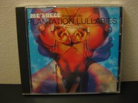
Soundtrack for the build: The Absolutely Essential 3 CD Collection - Django Rheinhardt (Figure 1)
Ready, get, set... (Figure 2)
And we're off! (Figure 3)
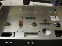
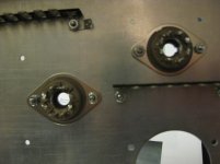
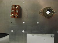
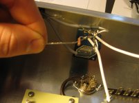
So I installed the hardware as instructed in the EXCELLENT manual (Figure 4), and ensured that the keyholes in the 8 pin tube sockets were facing away from the switch (Figures 5-7).
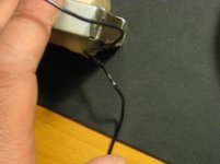
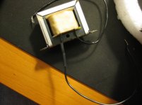
Then I installed the chokes as instructed (Figure 8)... But... OH NO! One of my chokes has a frayed wire (Figure 9).
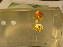
Moving past that I installed the RCA jacks (ensuring to install them in the order of the plastic washer, nut, grounding lug, and then the second nut as instructed, Figure 10).
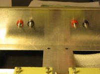
I then installed the binding posts (Figure 11) and the volume pot (Figure 12).
So, I'm stuck at this point. Should I order a replacement choke? Or should I simply heatshrink over the fray? Would that be safe? Before I proceed, I have to figure this out... Hopefully I can start the wiring tomorrow! Unless I have to order another Hammond choke... hmmm...
(Pictures will be posted in the subsequent posts...)
Today: Due to a crazy week at school/work, I didn't have time to install all the hardware into the chassis. Thus, today I tackled installing all the components...well MOST of the components.
Soundtrack for the build: The Absolutely Essential 3 CD Collection - Django Rheinhardt (Figure 1)
Ready, get, set... (Figure 2)
And we're off! (Figure 3)
So I installed the hardware as instructed in the EXCELLENT manual (Figure 4), and ensured that the keyholes in the 8 pin tube sockets were facing away from the switch (Figures 5-7).
Then I installed the chokes as instructed (Figure 8)... But... OH NO! One of my chokes has a frayed wire (Figure 9).
Moving past that I installed the RCA jacks (ensuring to install them in the order of the plastic washer, nut, grounding lug, and then the second nut as instructed, Figure 10).
I then installed the binding posts (Figure 11) and the volume pot (Figure 12).
So, I'm stuck at this point. Should I order a replacement choke? Or should I simply heatshrink over the fray? Would that be safe? Before I proceed, I have to figure this out... Hopefully I can start the wiring tomorrow! Unless I have to order another Hammond choke... hmmm...
(Pictures will be posted in the subsequent posts...)
An externally hosted image should be here but it was not working when we last tested it.
Attachments

Please send a photo of the frayed section so I can access the situation.
Thanks,
Scott
Thanks,
Scott
Alright, entry 2!
Today: Due to a crazy week at school/work, I didn't have time to install all the hardware into the chassis. Thus, today I tackled installing all the components...well MOST of the components.
Soundtrack for the build: The Absolutely Essential 3 CD Collection - Django Rheinhardt (Figure 1)
Ready, get, set... (Figure 2)
And we're off! (Figure 3)
So I installed the hardware as instructed in the EXCELLENT manual (Figure 4), and ensured that the keyholes in the 8 pin tube sockets were facing away from the switch (Figures 5-7).
Then I installed the chokes as instructed (Figure 8)... But... OH NO! One of my chokes has a frayed wire (Figure 9).
Moving past that I installed the RCA jacks (ensuring to install them in the order of the plastic washer, nut, grounding lug, and then the second nut as instructed, Figure 10).
I then installed the binding posts (Figure 11) and the volume pot (Figure 12).
So, I'm stuck at this point. Should I order a replacement choke? Or should I simply heatshrink over the fray? Would that be safe? Before I proceed, I have to figure this out... Hopefully I can start the wiring tomorrow! Unless I have to order another Hammond choke... hmmm...
(Pictures will be posted in the subsequent posts...)
An externally hosted image should be here but it was not working when we last tested it.


Figures 8-10
Just solder that back together and heat shrink it. It will be fine.
I am just about at the same build level for the same kit. I started on the signal input wires yesterday, and discovered I have misplaced my heat gun in my recent move.
Off to Home Depot for a new heat gun (just could not find my old one) and some black spray paint yesterday, and then the SuperBowl, no further work got done.
My kit has the colored chassis, and bell covers. I plan on painting the transformer sides, and the motor run caps black. Hopefully finish the input cables to the volume control tonight. Will wait a bit and see if the weather warms up before trying to spray paint a couple of nights in a row.
Keep up the great blog!
Update number 3!
Objective: Begin wiring!
Soundtracks to the build: Ozric Tentacles - Jurassic Shift, Charlie Hunter - Songs from the Analog Playground, and Roy Hargrove - Habana
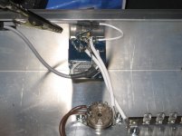
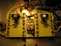
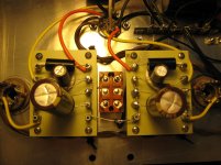
First I heatshrinked over the break in the choke wire (Figure 1). Good as new! I then installed the choke (Figure 2).
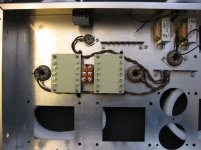
Now it was time to start soldering! First the RCA jacks (Figure 3). Then I installed the tie downs for the audio cable. (Figure 4). Finally I began wiring the volume control (Figure 5). I was progressing nicely when...SNAP! In trying to position the 1Mohm resistor, the lead snapped off at the resistor body (Figure 6).
Well... I'm out of commission for a while now... I am going to have to order another 1Mohm resistor. Additionally, in attempting to clean up the solder tabs on the volume control, I think I damaged it... I may need to install new leads from the RCAs to the volume pot as well... I'm not 100% sure on this though... Sigh... To say I'm frustrated would be quite an understatement.
I live in New England, and am thus hunkering down for the "Snowpocalypse," and was stoked to have three days to complete the amp while I was snowed in... I guess my plans have just changed! I now have to order some replacement parts... Off to the first post of scott17's thread to get part numbers...
Oh bother...
Objective: Begin wiring!
Soundtracks to the build: Ozric Tentacles - Jurassic Shift, Charlie Hunter - Songs from the Analog Playground, and Roy Hargrove - Habana
First I heatshrinked over the break in the choke wire (Figure 1). Good as new! I then installed the choke (Figure 2).
Now it was time to start soldering! First the RCA jacks (Figure 3). Then I installed the tie downs for the audio cable. (Figure 4). Finally I began wiring the volume control (Figure 5). I was progressing nicely when...SNAP! In trying to position the 1Mohm resistor, the lead snapped off at the resistor body (Figure 6).
Well... I'm out of commission for a while now... I am going to have to order another 1Mohm resistor. Additionally, in attempting to clean up the solder tabs on the volume control, I think I damaged it... I may need to install new leads from the RCAs to the volume pot as well... I'm not 100% sure on this though... Sigh... To say I'm frustrated would be quite an understatement.
I live in New England, and am thus hunkering down for the "Snowpocalypse," and was stoked to have three days to complete the amp while I was snowed in... I guess my plans have just changed! I now have to order some replacement parts... Off to the first post of scott17's thread to get part numbers...
Oh bother...

Update number 3!
Finally I began wiring the volume control (Figure 5). I was progressing nicely when...SNAP! In trying to position the 1Mohm resistor, the lead snapped off at the resistor body (Figure 6).
Well... I'm out of commission for a while now... I am going to have to order another 1Mohm resistor. Oh bother...
I broke the lead off one of those 1 Megohm resistors (blamed on my 10 big thumbs here 😱 ). I went to Radio Shack and got some of theirs with the same wattage rating. Out of 10, I managed to find a few closely matched pairs (using my multi-meter), and replaced both. Problem solved, no waiting on an order. Used them for several months, with no problem.
btw - nice progress!
Last edited:
Yes, Dave is correct. Any 1M resistor will work in that location. It will not affect the way the amp sounds or performs.
Update Number 4
Objective: Pick up the pieces and soldier on!
Soundtrack of the build: Django Rheinhardt and Stephane Grapelli - Souveniers, Alicia Keys - As I Am, Dixie Dregs - California Dreamin', Shai - If I Ever Fall In Love
So, when I snapped the resistor yesterday morning, I was very frustrated, and thought I'd ruined my amp. After some encouragement and advice from scott17 and dave R, I dug through my parts drawer and found a 1mohm resistor! Thus I soldiered on...under an 18+ blanket of snow (I'm in Rhode Island).
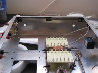
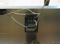
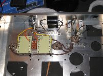
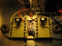
That said, my volume control is one ugly duckling. I don't anticipate any functionality issues, but, if I find that there are some, I can always order a replacement volume control and rewire. (Figure 1).
I then kinda zoned out and boom...progress... I forgot to take pictures at each step...OOOPS! Figures 2-8.
I then installed the caps. Figure 9.
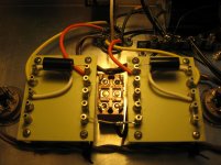
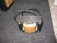
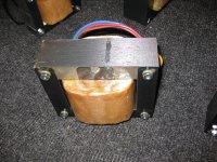
Then, I wanted to install the transformers and choke, but I got a bit confused. I am not exactly sure how to install the nylon spacers as it seems as though some of the transformers have spacers pre-installed? Maybe you guys and gals can point me in the right direction? Figures 10-13.
Phew. I feel like I can see the light at the end of the tunnel! I can't wait to finish soldering to get to testing! If I can get this running, I'll get to test out my turntable (Vintage Direct Drive P Mount Technics I got at a Flea Market for $15). Oh and my new speakers!
Objective: Pick up the pieces and soldier on!
Soundtrack of the build: Django Rheinhardt and Stephane Grapelli - Souveniers, Alicia Keys - As I Am, Dixie Dregs - California Dreamin', Shai - If I Ever Fall In Love
So, when I snapped the resistor yesterday morning, I was very frustrated, and thought I'd ruined my amp. After some encouragement and advice from scott17 and dave R, I dug through my parts drawer and found a 1mohm resistor! Thus I soldiered on...under an 18+ blanket of snow (I'm in Rhode Island).
That said, my volume control is one ugly duckling. I don't anticipate any functionality issues, but, if I find that there are some, I can always order a replacement volume control and rewire. (Figure 1).
I then kinda zoned out and boom...progress... I forgot to take pictures at each step...OOOPS! Figures 2-8.
I then installed the caps. Figure 9.
Then, I wanted to install the transformers and choke, but I got a bit confused. I am not exactly sure how to install the nylon spacers as it seems as though some of the transformers have spacers pre-installed? Maybe you guys and gals can point me in the right direction? Figures 10-13.
Phew. I feel like I can see the light at the end of the tunnel! I can't wait to finish soldering to get to testing! If I can get this running, I'll get to test out my turntable (Vintage Direct Drive P Mount Technics I got at a Flea Market for $15). Oh and my new speakers!
Then, I wanted to install the transformers and choke, but I got a bit confused. I am not exactly sure how to install the nylon spacers as it seems as though some of the transformers have spacers pre-installed? Maybe you guys and gals can point me in the right direction? Figures 10-13.
Bryan,
Remove all existing hardware from the transformers, including the spacers, and use the new hardware and spacers. The new nylon spacers install only on the top, through the end bells.
You sound like you are making great progress. I guess the photos did not make it through.
Scott
Figures 1-9
Attachments
-
 IMG_0397.jpg614.9 KB · Views: 150
 -
 IMG_0398.jpg731.9 KB · Views: 132
 -
 IMG_0401.jpg809.6 KB · Views: 131
 -
 IMG_0408.jpg635.4 KB · Views: 118
 -
 IMG_0412.jpg581.2 KB · Views: 113
 -
 IMG_0414.jpg661.4 KB · Views: 97
 -
 IMG_0415.jpg719.1 KB · Views: 105
 -
 IMG_0416.jpg710.2 KB · Views: 119
 -
 IMG_0420.jpg830.3 KB · Views: 186

Oh, and one more question. I haven't yet secured the larger caps on the turret board with the silicone based adhesive as advised in the manual. Does anyone have a favorite brand? The other hiccup I had was that, as discussed in the manual, the mount for one of the filter caps needs to be bent so that it can be tightened down. I couldn't get the tabs bent such that I could include a lockwasher, so I had to just use the normal nut without a lockwasher. I don't think that this should be a problem, but, feel free to correct me if I'm wrong!
You don't really have to use any at all as they won't really be under any stress. If you want to though, any general purpose RTV silicone will work.
The cap mount should be fine, or get a longer bolt.
The cap mount should be fine, or get a longer bolt.
Oh, and one more question. I haven't yet secured the larger caps on the turret board with the silicone based adhesive as advised in the manual. Does anyone have a favorite brand? The other hiccup I had was that, as discussed in the manual, the mount for one of the filter caps needs to be bent so that it can be tightened down. I couldn't get the tabs bent such that I could include a lockwasher, so I had to just use the normal nut without a lockwasher. I don't think that this should be a problem, but, feel free to correct me if I'm wrong!
- Status
- Not open for further replies.
- Home
- Amplifiers
- Tubes / Valves
- Scott17 KT88 SE Tube Amp Build Log