I'm just asking because I see +-45V on the pcb. So +-35V would be OK?
Hi. Yes 35V should be okay.
Hi shaan,
I need a favour from you. My laser printer doesn't print very dark so I have to print twice in the same sheet of paper. Your pcb layouts are at the middle of the pdf sheet and I can't get the two printouts aligned. Could you please send me a pdf with the layout on the top of the sheet so the disalignment is smaller?
Thank you.
But is 45V the prefered voltage? I'm not clear why the rails change from 28V to 45V...😕 What is the optimum voltage?Hi. Yes 35V should be okay.
what is optimum is not fixed, it depends upon several other factors.
How loud u want the music, how sensistive are you speakers, what the impedance of ur speakers is, how much you want to bias the amp towards class A, How big are your heatsinks ?
But to cut a long story short + / - 35V will be a pretty good starting place for an average kind of a set up.
How loud u want the music, how sensistive are you speakers, what the impedance of ur speakers is, how much you want to bias the amp towards class A, How big are your heatsinks ?
But to cut a long story short + / - 35V will be a pretty good starting place for an average kind of a set up.
Last edited:
Hi mikelm,
How much rail voltage would be fine with just one pair of 2SJ162/SK1058 (this version of the SSA only has one pair) for 4 Ohms duty? Isn't 45V a bit too high?
How much rail voltage would be fine with just one pair of 2SJ162/SK1058 (this version of the SSA only has one pair) for 4 Ohms duty? Isn't 45V a bit too high?
The issue is not to be "loud enough" ist about safety. I don't want to blow up the output transistors. First I was thinking in using my 300VA 25-0-25V transfomer wich gives me +-35V dc and myabe regulate the voltage to +-30V so it would be close enough to the 28V of the schematics. Then I saw on the servo pcb +-45V and I tought - I have two 300VA 35-0-35V transformers, if I would use them and regulate the voltage to +-45V I could make a dual mono setup and have more sound quality. But isn't 45V too much specialy with 4Ohms speakers?
Hi paulo.
I got your PM. But I'm sorry to say that right now I am typing from my cellphone and am far away from home, so can't help you with printing problems. Please don't mind.
Here are the answers to some of your previous questions.
I guess ESP P101 can deliver 150w because the FET's Safe Operating Area or SOA allows it at pulses shorter than 50mS or at 20Hz and above with 70v PS rails.
The 45V mod was the result of a fellow diy-er's request. You can safely run the amp from 35V rails into 4ohm with a single pair of FETs.
Happy listening.
shaan
Hi shaan.
No worries. Thank you for your kind help. 🙂I got your PM. But I'm sorry to say that right now I am typing from my cellphone and am far away from home, so can't help you with printing problems. Please don't mind.
Hi paulo.
.
....................................................... You can safely run the amp from 35V rails into 4ohm with a single pair of FETs.
Happy listening.
shaan
Hi Shan,
I too know little about solid state design and especially heat-sink requirements. Run as shown in red in the quote above, what is a safe minimal heat-sink requirement per channel?
I can wait until you return for a response!
Many thanks.
Hi Shan,
I too know little about solid state design and especially heat-sink requirements. Run as shown in red in the quote above, what is a safe minimal heat-sink requirement per channel?
I can wait until you return for a response!
Many thanks.
Hi brianco.
My rough guess is a 0.5degC/W heatsink per channel. You can see I am no expert in heatsink designing. However, I use a p4 CPU heatsink with the 12v fan running at 6v, per channel. And this works well at full power output. If you try this I doubt you'll be disappointed. 😉
shaan
Thank you Shan...I am sure your temperatures 'near the Ganges' are a lot higher than ours here in Scotland!
That gives me a good clue that the heatsinks I already have will do - at least for testing.
That gives me a good clue that the heatsinks I already have will do - at least for testing.
My pleasure Brian. But, do you really need heatsinks in Scotland? Well London may need sinks though, in mid summer. 😉 😀
It is very simple. If V is the power supply voltage ( "V+" + "V-" ), and Rl the impedance load, the max dissipated power will be: Wdiss = V²/(19.75 x Rl). for a class B amp.You can see I am no expert in heatsink designing.
You add the thermal resistance of the device, isolator if any, and radiator and you get the total thermal resistance. Now, it is easy to calculate the max temperature.
Last edited:
If you allow the temperature junction to reach 150° when atmospheric air is at 50°, you need a temperature delta of 100°.
You have to know the power of your transistor at 25°. Now, you divide 25 by this power to know the internal thermal resistance of your transistor. lets call this "K"
You add the thermal resistance between the case of your power device and the radiator for a mounting with thermal grease. Lets call this 'D"
Multiply this D value by two if you add a isolation material, and add the thermal resistance of the isolator itself.
Now, you have the total thermal resistance of the mounted transistor by adding "K"+"D" = "R".
Divide this value by the number of power device you will use: "S".
P is the power value you need, according to the last post.
We need "T"= 100/P of total thermal resistance.
T-S will give-you the maximum desired thermal resistance of your radiator. Any value less than that will feat.
Yes, i know, it is boring to calculate.
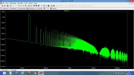
Hi paulo. We need to see the schematic you are simulating. At what output voltage and load resistance was this FFT taken?
H2 is at -75dB from the signal level, (<0.02%) what the hell ?I've been doing simulations with LTSpice. I get a lot of harmonics.
Last edited:
- Status
- Not open for further replies.
- Home
- Amplifiers
- Solid State
- Simple Symetrical Amplifier