I use a small grid stopper, 390R. It may not be necessary - I haven't looked into this. You absolutely have to have a grid leak or the tube will oscillate. I have a 100K pot on the input so that acts as grid leak.
You can use up to 60uF cap with the AZ1. Normally a small cap is good so you have choke input or "virtual" choke input. If you do this you have to make sure the choke is in regulation - may need to be followed by a resistor to earth probably somewhere round 10K and needs to have sufficient wattage.
But since this is followed by chokes, caps and a shunt reg (or DN2540 + glow tube), it may not be too audible. If you need to keep the HT high enough then sure, you can use a bigger first cap. If you have plenty of voltage you might go for a "purist" approach and use choke input or a cap up to 1uf or so. Plenty of choices, and they all work.
Are you saying you have two transformers both 125vAC? You could put the secondaries in series to get 250v. You would need to get the phase right - if you have 2 identical transformers the end of the first winding should go to the start of the second winding.
Last edited:
I use a small grid stopper, 390R. It may not be necessary - I haven't looked into this. You absolutely have to have a grid leak or the tube will oscillate. I have a 100K pot on the input so that acts as grid leak.
You can use up to 60uF cap with the AZ1. Normally a small cap is good so you have choke input or "virtual" choke input. If you do this you have to make sure the choke is in regulation - may need to be followed by a resistor to earth probably somewhere round 10K and needs to have sufficient wattage.
But since this is followed by chokes, caps and a shunt reg (or DN2540 + glow tube), it may not be too audible. If you need to keep the HT high enough then sure, you can use a bigger first cap. If you have plenty of voltage you might go for a "purist" approach and use choke input or a cap up to 1uf or so. Plenty of choices, and they all work.
Andy if I not use pot wich value for grid leak resistor 100K?
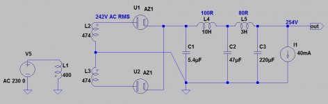
I'd say more like this, with 250v secondary. I use all polypropylene caps - motor runs. The 10K resistor after the first choke is probably overkill - it depends on what the circuit draws in terms of current. I don't know what the shunt reg draws. You could leave out the 1uF input cap or use somewhere between 0.1 and 1uF. I like to put a small cap in there. Choke input with 250v secondary should end up giving you just over 200v with all the chokes, caps, resistors etc, before the shunt reg. That would be fine for a DN2540 plus 150v glow tube. Don't know about a Salas reg - never used one. If the voltage ends up being low (the resistor after the choke will lower the voltage depending what size it is) you can increase the size of the first cap. You need to read about how to keep chokes in regulation and look at the formula for choke input. For cap input above about 4uF it probably doesn't matter. I'm being a bit vague about this because I have a Mac and can't run the PSU calculator.
Attachments
Last edited:
The SSHV2 reg draws itself 20mA, psud2 can't simulate the 10K 14W but can simulate a constant current: do you know the mA to calculate with psud2?
Andy if I not use pot wich value for grid leak resistor 100K?
Anything from 100K to 470K.
Here is an article for choke input. You need to work out critical inductance.
Choke-input power supplies, Part 1 - Henry Pasternack - Tube DIY Asylum
Lcrit = Vdc / Ima
where Lcrit is the minimum (critical) choke inductance, Vdc is the supply DC output voltage, and Ima is the load current in milliamperes.
So Lcrit for 250v and 33mA (e.g. 2 x 26 at 5mA plus regulator at 23mA) would be 7.6 Henries. So a 10H choke would be fine without a resistor to earth after it in this case.
For 2 x 26 at 5mA each and 20mA shunt reg, total 30mA, you need a choke of 8.3H so again 10H is OK.
Last edited:
Thank you Andy, BTW Bartolucci 10H 100mA have:
-Regulation 0,5%
-VDC 200
-DC resistance 10 ohms
Are ok?
-Regulation 0,5%
-VDC 200
-DC resistance 10 ohms
Are ok?
Last edited:
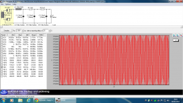
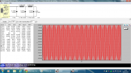
Ale I have simulated your PSU, simulator saids have more ripple, or I'm misunderstanding something, see attached image.
Attachments
Last edited:
Felipe, that's not my design. Either way 12mvpp ripple is not bad at all! Are you planning to use a shunt regulator?
Ale
Ale
Felipe, can I do some comments?
Such a low transformer DCR not optimal for (mesh) AZ1. It would be better 100-200R DCR.
IMHO C1 low, thus output voltage also low. There are no high charging current (AZ1 unable to do so) therefore increase C1 up to 1-5uF. If output ripple bothering you, increase C3.
ps. PSUD a little cheating, output voltage about 220V, not 230.
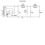
Ps2. Attachment is my working #26 preamp (common raw PSU- each side: SSHV2- cascode CCS loaded 26 -TVC) raw HT supply.
Such a low transformer DCR not optimal for (mesh) AZ1. It would be better 100-200R DCR.
IMHO C1 low, thus output voltage also low. There are no high charging current (AZ1 unable to do so) therefore increase C1 up to 1-5uF. If output ripple bothering you, increase C3.
ps. PSUD a little cheating, output voltage about 220V, not 230.
Ps2. Attachment is my working #26 preamp (common raw PSU- each side: SSHV2- cascode CCS loaded 26 -TVC) raw HT supply.
Attachments
Euro21 has a fine design there. The only thing I would question is not using polypropylene caps, especially as the last cap. Maybe the 220uF is polypropylene, though. I just put in 40uf caps because I have a box of them. It's easy to parallel up caps, though polypropylenes caps get big. But motor runs are not expensive, and 220uF is certainly a nice kind of value.
Try to add resistances and inductances of wires into your SIM, variable current drawn, and you will see why ground sign have to be drawn near C3 instead of near C1.
I have the B+, L/R filaments and remote control power all in the same umbilical, with each pair twisted and shielded. Coleman supplies have 1000uF cap at input, B+ is regulated with VR tubes in the preamp chassis, 26s have cascoded CCS plate loads. My filament supply has ~10mV of ripple when it exits the PS chassis. The pre is dead quiet.
Magz very nice build, do you know what the output Z is?
Magz very nice build, do you know what the output Z is?
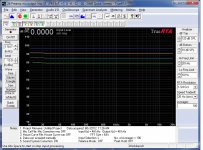
The output Z varies based on the volume setting, since I'm using the autoformer volume controls as my output "transformer" as well as a volume control. The autoformer is fed from the mu output of the 26 plate CCS in lossy parafeed, so the output Z at 0dB attenuation will be about 1500ohm, at -6dB about 375ohm, at -12dB about 94ohm, etc. I usually listen with the preamp volume control between -20 to -6dB, so the output z is less than 375ohm almost all of the time.
I've attached a frequency response plot at various volume control settings, from top to bottom -6, -12, -18, -24dB. The input impedance of my soundcard interface is 20kohm.
Attachments
Last edited:
The output Z varies based on the volume setting, since I'm using the autoformer volume controls as my output "transformer" as well as a volume control. The autoformer is fed from the mu output of the 26 plate CCS in lossy parafeed, so the output Z at 0dB attenuation will be about 1500ohm, at -6dB about 375ohm, at -12dB about 94ohm, etc. I usually listen with the preamp volume control between -20 to -6dB, so the output z is less than 375ohm almost all of the time.
I've attached a frequency response plot at various volume control settings, from top to bottom -6, -12, -18, -24dB. The input impedance of my soundcard interface is 20kohm.
Cheers, didn't realize you were using the AVCs on the output. I'll have to read through the last 30 pages of this thread to catch up.
- Home
- Amplifiers
- Tubes / Valves
- #26 pre amp