I bring earth into amp through iec socket and go straight to chassis with it for ground...
My HT secondary winding has center tap and this goes to chassis through 500mA fuse
the heater windings have no CT.
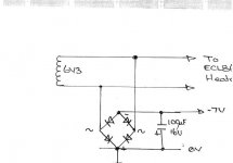
One of the 6.3Vac heaters supplies goes to heaters but I am also placing a bridge rectifier in the circuit and referencing the positive of this to Ground and therefore getting -7V for a ccs that i need.
The OV for the B+ is referenced from ground....
Does this sound correct?
Thanks in advance - Stuart
My HT secondary winding has center tap and this goes to chassis through 500mA fuse
the heater windings have no CT.
One of the 6.3Vac heaters supplies goes to heaters but I am also placing a bridge rectifier in the circuit and referencing the positive of this to Ground and therefore getting -7V for a ccs that i need.
The OV for the B+ is referenced from ground....
Does this sound correct?
Thanks in advance - Stuart
My HT secondary winding has center tap and this goes to chassis through 500mA fuse
The center tap to ground is fused?
The center tap to ground is fused?
Heater/filament windings are often grounded on one end or through the center tap if available. Referencing the heater to ground is done to reduce hum problems were they to exist. You can do what you propose as long as the heater wiring is not grounded at any other point you are not aware of. Of course you will need some filtering for this negative voltage source.what I'd really like to know: can you force one end of a heater winding to be ground?
Why fuse the center tap other than a false sense of security and if your current power transformer doesn't have a tap, I'd add a small separate transformer to power the CCS you need and leave the filament alone.
@N4BBQ - I was going to fuse the center tap simply because the original circuit from where i took the transformer from had a fuse here... I was just going to copy the gz34 circuit but add my own filterting section that I've established from PSUD2 - if you guys have a better idea then I am all ears as I am still wrestling with my noob status..
@hollowstate ... thankyou, I figured I could do this - the heaters are not connected to ground anywhere else as this is a build from scratch. I think I am clear now - My 0V is always connected to the chassis for ground although I've heard it is wise to still run the 0V through the amp on its own wire and drop to ground after each section?
The transformer has 2 6.3Vac supplies and a 5Vac for the gz34
I have used one 6.3Vac for vu meters and the rermaining 6.3Vac will supply 4 ecl86 heaters in parallel but before it reaches them there will be a bridge across it with the positive connected to 0V bus and negative to supply my -7V ccs (3mA)
Thanks for everyones input, I just thought that putting a CT from main secondary to the same bus as an anode side of one of the 6.3Vac might be stupid, but obviously not...
Stuart
Stuart,
Assuming that one 6 volt winding is for the VU meter (lamps only?), why not use that 6 volts for the rectified negative source. The circuit would probably perform better hum wise with the heaters referenced directly to ground. The bridge gives you only ½ cycle to ground.
Assuming that one 6 volt winding is for the VU meter (lamps only?), why not use that 6 volts for the rectified negative source. The circuit would probably perform better hum wise with the heaters referenced directly to ground. The bridge gives you only ½ cycle to ground.
Thanks hollowstate...
well, I'm just working from a suggestion from the guy who drew the schematic for the ecl86 huey I'm building so I thought I would go with his option, I just wasn't sure about putting it on the same 0V bus as the rectified B+
You've cleared it up for me i think so cheers
well, I'm just working from a suggestion from the guy who drew the schematic for the ecl86 huey I'm building so I thought I would go with his option, I just wasn't sure about putting it on the same 0V bus as the rectified B+
You've cleared it up for me i think so cheers
Attachments
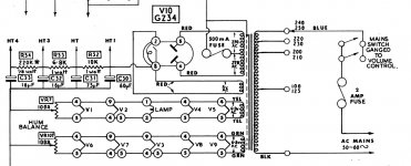
N4BBQ - have attached original circuit where the transformer was taken from... maybe I do not need the 500mA fuse?
Just a fuse on the AC inlet?
stuart
Fusing the secondary is a good thing. However, a fuse in the centre tap only protects against some types of fault such as excessive DC current taken from the rectifier. It would not protect the transformer if the rectifier valve or wiring developed a short between the two anode voltages. I would put a fuse in each AC line to the rectifier, and no fuse in the centre tap connection to ground. That way you are providing greater protection for the transformer.
My HT secondary winding has center tap and this goes to chassis through 500mA fuse
The center tap to ground is fused?
...and goes to the ground, instead of going to the filter capacitor?
Thanks I2e1, I will look into fusing both secondary anodes - is this the usual?
Wavebourn - if you mean CT to negative of capacitor (ground) then yes?
Wavebourn - if you mean CT to negative of capacitor (ground) then yes?
N4BBQ - have attached original circuit where the transformer was taken from... maybe I do not need the 500mA fuse?
Just a fuse on the AC inlet?
stuart
I see that. Well that will definitely turn everything off in case of a failure that exceeds 500mA in the CT, but it leaves a lot of dangerous voltages present.
I'd not fuse the CT; I'd just fuse the AC line coming in and leave it at that.
Here's a nice tutorial on safe power supply design and proper metering (RF-based tube amps, but you can apply the techniques to audio).
Metering amplifier or transmitter
Metering amplifier or transmitter
The high voltage secondary CT should go to the first (reservoir) capacitor negative terminal, not ground. Unless you like some buzz wih your music!
Simply grounding the CT may have been the practice in the 1950s, when people expected a little buzz with music. Now we know that we don't have to put up with this, with correct grounding.
Simply grounding the CT may have been the practice in the 1950s, when people expected a little buzz with music. Now we know that we don't have to put up with this, with correct grounding.
thanks N4BBQ, just been reading up, its in the same style writting as the neets pages used by royal navy..
Stuart
Stuart
Thanks DF96, think I may also fuse both HV secondary anodes pre rectifier valve with 500mA
Should I use slow blow or quick blow?
Stuart
Should I use slow blow or quick blow?
Stuart
I don't know. I would not put a fuse there. When you put a fuse in you have to ask "what am I trying to protect, and from what?".
Thanks DF96, think I may also fuse both HV secondary anodes pre rectifier valve with 500mA
Should I use slow blow or quick blow?
Stuart
I use quick-blow fuses in my amp (2 x GZ34 rectifiers, 4 x EL34 for output).
DF96 wouldn't use them there - that's his choice. As he says, it depends what you want to protect, and I wanted to protect an irreplaceable mains transformer against any faults that bad wiring or faulty components might be able to introduce. So I have 500mA between transformer and the rectifier anodes. I've blown then a couple of times - but only when a meter probe slipped while checking voltages.
Wavebourn - if you mean CT to negative of capacitor (ground) then yes?
Yes. The wire should go directly to it, not through some other ground wire that is common for something else, since charging pulses are quite high current and cause on wires quite noticeable voltage drops.
- Status
- Not open for further replies.
- Home
- Amplifiers
- Tubes / Valves
- Quick question about grounding