The LM317 and LM337 commonly used to make a +/- power supply are pretty old now. I see lot of the more modern DACs are using newer low noise regulators like the LT1963 etc.
Does anyone know of a newer set of positive/negative regulators that are superior for audio use?
Does anyone know of a newer set of positive/negative regulators that are superior for audio use?
I won't throw any rocks at the LM317/337 -- but we found that the Linear Tech LT1963A and LT3015 provided the most pleasing sound of any OEM 3-legged regulator when compared with 12 of their peers.
Noise is the least important criteria -- output impedance and PSRR seem to be more important factors in empirical evaluation of regulators. Nevertheless, listening always wins. There were regualtors which tested superbly but really screwed with the sound.
Noise is the least important criteria -- output impedance and PSRR seem to be more important factors in empirical evaluation of regulators. Nevertheless, listening always wins. There were regualtors which tested superbly but really screwed with the sound.
I won't throw any rocks at the LM317/337 -- but we found that the Linear Tech LT1963A and LT3015 provided the most pleasing sound of any OEM 3-legged regulator when compared with 12 of their peers.
Noise is the least important criteria -- output impedance and PSRR seem to be more important factors in empirical evaluation of regulators. Nevertheless, listening always wins. There were regualtors which tested superbly but really screwed with the sound.
Ah that's what I wanted! I couldn't find the negative counterpart for the LT1963A.
Yes, these sound nice:tps7a3001, tps7a4901 ;-)
"One of the primary TPS7A30xx applications is to provide ultralow noise voltage rails to high-performance analog circuitry in order to maximize system accuracy and precision. In conjunction with its positive counterpart, the TPS7A49xx family of positive high-voltage linear regulators, the TPS7A30xx family of negative high voltage linear regulators provides ultralow noise positive and negative voltage rails to high-performance analog circuitry, such as operational amplifiers, ADCs, DACs, and audio amplifiers."
They only come in MSOP-8 package though, at 3x3mm, it would be tricky to solder.
Thanks for the suggestions!
as I said - you don't need "the negative counterpart" you can use the same type for both polarity supplies by floating both secondary windings with respect to each other
which allows you to use the best reg you can find for both supplies - and use the same part # in both
which allows you to use the best reg you can find for both supplies - and use the same part # in both
Last edited:
They only come in MSOP-8 package though, at 3x3mm, it would be tricky to solder.
It's not only MSOP-8, but also the exposed PowerPAD that makes it even trickier to solder.
Noise is the least important criteria
On my CD transporter, I use an OP-based pre-reg and compare the LT1085-CT5 with LT1763-5. The result from LT1763-5 is quite impressive, much quieter than LT1085. I guess noise is important for digital part.
as I said - you don't need "the negative counterpart" you can use the same type for both polarity supplies by floating both secondary windings with respect to each other
which allows you to use the best reg you can find for both supplies - and use the same part # in both
I've seen this used in a Gainclone before but why isn't this approach taken very often? Transformers with dual secondaries are pretty standard these days but you never see this used in datasheets or elsewhere?
Ah that's what I wanted! I couldn't find the negative counterpart for the LT1963A.
There is one small hiccup to watch out for if you wind up using the LT1963A and LT3015. The maximum input voltage on the LT3015 is -30Vdc while the LT1963A is only +20Vdc.
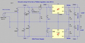
I'm doing a design and layout right now with both parts being fed by a 16Vac half wave and I want +/-16Vdc out. That results in the incoming ripple going from 20.5Vdc to 21.5Vdc, too much for the LT1963A but OK for the LT3015 on the negative rail (-20.5Vdc to -21.5Vdc). So I borrowed the great idea that pete_shumacher recently posted here for his power filter of a diode (LED) drop from the rail feeding a series pass to drop 3V of incoming voltage for the LT1963A. So now it gets ripple that goes from 17.0Vdc to 18.0Vdc. Problem solved. 🙂
Attachments
There is one small hiccup to watch out for if you wind up using the LT1963A and LT3015. The maximum input voltage on the LT3015 is -30Vdc while the LT1963A is only +20Vdc.
You can use the LT1963A to regulate a higher voltage -- just use it to regulate a portion of the output voltage a la Maida. I did this with a DH-110 preamplifier to replace the LM317/LM337 which regulate a discrete preamplifier. The output impedance will be different, however.
As there was no negative regulator counterpart for the LT3080 floating regulator, we didn't include it in the Linear Audio test. The test setup, however, could be changed a little bit as the transformer has two separate windings. (If the test id done again, I would love to incorporate Walt Jung's shunt regulator described in AudioXpress a few months ago.)
There is one small hiccup to watch out for if you wind up using the LT1963A and LT3015. The maximum input voltage on the LT3015 is -30Vdc while the LT1963A is only +20Vdc.
I'm doing a design and layout right now with both parts being fed by a 16Vac half wave and I want +/-16Vdc out. That results in the incoming ripple going from 20.5Vdc to 21.5Vdc, too much for the LT1963A but OK for the LT3015 on the negative rail (-20.5Vdc to -21.5Vdc). So I borrowed the great idea that pete_shumacher recently posted here for his power filter of a diode (LED) drop from the rail feeding a series pass to drop 3V of incoming voltage for the LT1963A. So now it gets ripple that goes from 17.0Vdc to 18.0Vdc. Problem solved. 🙂
You likely want to add 10 nF capacitors from the ADJ pins to ground: Linear's data sheets indicate noise output is lower and transient response better with those in the circuit.
Last edited:
You likely want to add 10 nF capacitors from the ADJ pins to ground:
Thanks for the heads-up! I did forget those caps.
You can use the LT1963A to regulate a higher voltage -- just use it to regulate a portion of the output voltage a la Maida. I did this with a DH-110 preamplifier to replace the LM317/LM337 which regulate a discrete preamplifier. The output impedance will be different, however.
I've been wondering if having the pre-regulator on the positive side would have an effect on the output impedance of the regulator. I should do some tests.
Last edited:
I read from a TI application note that low drop out (LDO) regulators have common emitter output, while regulators like LM317/337 have common collector output. So there are two things to watch for - LDOs may have higher output impedance and the output capacitor may have a much bigger impact on performance as it is part of the close loop gain of a common emitter circuit.
I don't know how regulators can be compared because different regulators require different implementations. I have been using LM317/337 and got very different results by implementating in different ways.
I would love to try the LT1936, TPS7XXX, etc, if they published some impedance curves like those in the LM317/337 datasheets. They don't publish the data which make it suspicious. At least from the impedance curves I can work out the optimal output capacitors, but without the data I wouldn't know how to use them properly therefore dont' want to give them a try.
These regulators all have inductive output. So with the output capacitor they form some LCR tuned circuit that requires some damping from the ESR of the output capacitor. This one alone has a dramatic impact on the perceived sound quality of the regulator. I need their data to work with them.
Regards,
Bill
Last edited:
I would love to try the LT1936, TPS7XXX, etc, if they published some impedance curves like those in the LM317/337 datasheets.
I put the impedance curve for the LT1963A and LT3015 in the LA article, and they are archived on Jan's site.
Online Articles
These regulators all have inductive output. So with the output capacitor they form some LCR tuned circuit that requires some damping from the ESR of the output capacitor. This one alone has a dramatic impact on the perceived sound quality of the regulator. I need their data to work with them.
They're all inductive. Zout is a function of the loop gain (amongst other things.)
re dual secs & bridges allows single polarity reg
the only downside I can see is that Kelvin sensing can't be used on gnd - the polarity of the feedback is wrong for one reg
I've seen this used in a Gainclone before but why isn't this approach taken very often? Transformers with dual secondaries are pretty standard these days but you never see this used in datasheets or elsewhere?
the only downside I can see is that Kelvin sensing can't be used on gnd - the polarity of the feedback is wrong for one reg
Last edited:
Jackinnj,
Thank you for the information.
I have built the Jung regulator. It worked fine by itself but as soon as a film cap was put at the load the regulator resonated. I used 2-7 opamps in my circuits and I did according to opamp manufacturers' datasheets to put a 0.1uF ceramic / MKP at the opamp legs. Since the Jung regulator does not like it that way I had to look for alternatives.
Out of all the regulators you measured and published which series regulators allow high Q film cap at their outputs? and which had the subjectively best sound?
It looks like the Pooge reg is worth trying. Does it allow film caps at its output?
Previously, I came back to the LM317/337 again and again for one reason or another.
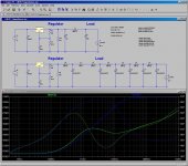
Attached are the schematic and simulation of my alternative ways to implement it. One graph is in ohms, and the other is identical but in dBs. The red curve is the standard implementation, and the green curve is the alternative implementation.
The idea is that if using LM317/337 we have no choice but rely on using capacitors at higher frequencies. So let us put some small, miniature type, low impedance electrolytic capacitors near the opamp legs. In that way we don't need to worry about film capacitors. The lowest impedance caps I found was Rubycon ZLH 560uF/25V dia=8mm Z=0.029R. This size is not too small but is small enough to be still manageable. Smaller size caps would have higher impedance, and bigger caps would be too large in physical size. These caps provide a lower impedance at the load. Of course, they would create a large, nasty peak in impedance within the audioband. The fix is to install a snubber at the regulator output. The capacitor required for the snubber is very large. We need to find the right capacitor with the right amount of ESR here (0.01R is ideal).
Comparing to the standard LM317/337 implementation, this alternative is much better. The standard implementation assumes Cadj=470uF, Cout=10uF (ESR=0.5R), Cload=100uF (Z=0.2R). If R(Cload) <0.18R or much larger than 0.2R there would be an impedance peak in the audioband. The alternative implementation has an impedance no more than about 10mR up to 20kHz, and no more than 20mR up to 100kHz.
I use opa627. It has a PSSR 78dB at 20kHz and 64dB at 100kHz. My way of implementing the LM317/337 provides 42dB at 20kHz and 36dB at 100kHz, combined with the opamp PSSR I have basically 100dB or better PSSR right up to 100kHz, which is not bad. There is no signal above 40kHz. So noise above 100kHz can be dealt with by using passive components before the LM317/337 regs. A small inductor of 47uH in a CLC circuit would deliver very good noise surpression result above 100kHz.
But then a regulator can never be good enough for audio. So I am still curious about finding a better regulator to use.
Regards,
Bill
Thank you for the information.
I have built the Jung regulator. It worked fine by itself but as soon as a film cap was put at the load the regulator resonated. I used 2-7 opamps in my circuits and I did according to opamp manufacturers' datasheets to put a 0.1uF ceramic / MKP at the opamp legs. Since the Jung regulator does not like it that way I had to look for alternatives.
Out of all the regulators you measured and published which series regulators allow high Q film cap at their outputs? and which had the subjectively best sound?
It looks like the Pooge reg is worth trying. Does it allow film caps at its output?
Previously, I came back to the LM317/337 again and again for one reason or another.
Attached are the schematic and simulation of my alternative ways to implement it. One graph is in ohms, and the other is identical but in dBs. The red curve is the standard implementation, and the green curve is the alternative implementation.
The idea is that if using LM317/337 we have no choice but rely on using capacitors at higher frequencies. So let us put some small, miniature type, low impedance electrolytic capacitors near the opamp legs. In that way we don't need to worry about film capacitors. The lowest impedance caps I found was Rubycon ZLH 560uF/25V dia=8mm Z=0.029R. This size is not too small but is small enough to be still manageable. Smaller size caps would have higher impedance, and bigger caps would be too large in physical size. These caps provide a lower impedance at the load. Of course, they would create a large, nasty peak in impedance within the audioband. The fix is to install a snubber at the regulator output. The capacitor required for the snubber is very large. We need to find the right capacitor with the right amount of ESR here (0.01R is ideal).
Comparing to the standard LM317/337 implementation, this alternative is much better. The standard implementation assumes Cadj=470uF, Cout=10uF (ESR=0.5R), Cload=100uF (Z=0.2R). If R(Cload) <0.18R or much larger than 0.2R there would be an impedance peak in the audioband. The alternative implementation has an impedance no more than about 10mR up to 20kHz, and no more than 20mR up to 100kHz.
I use opa627. It has a PSSR 78dB at 20kHz and 64dB at 100kHz. My way of implementing the LM317/337 provides 42dB at 20kHz and 36dB at 100kHz, combined with the opamp PSSR I have basically 100dB or better PSSR right up to 100kHz, which is not bad. There is no signal above 40kHz. So noise above 100kHz can be dealt with by using passive components before the LM317/337 regs. A small inductor of 47uH in a CLC circuit would deliver very good noise surpression result above 100kHz.
But then a regulator can never be good enough for audio. So I am still curious about finding a better regulator to use.
Regards,
Bill
Attachments

Last edited:
I have built the Jung regulator. It worked fine by itself but as soon as a film cap was put at the load the regulator resonated.
I've used the Jung regulators with X7R 0.1uF ceramic bypass caps at the load and have not experienced any oscillation. One such example is my modded up Adcom GFP-565 preamp (a la Galo's thoughts from AX a few years ago.)
If you put a a film cap on the output of the Jung regulator it "may" oscillate. If you put a ceramic cap right at the opamp it most likely will not oscillate. There is inductance and resistance of about 10nH/cm 40mR/cm which decouple the regulator a bit.
If you're going to DIY a Jung regulator, I would pay close attention to the layout of Jan's implementation in part 3. This is a very high gain, broadband circuit and the layout was carefully designed to take this into account. Unfortunately, the Old Colony boards are no longer available, but the template can be found archived on Walt's website.
One thing about bypass which is important to note -- passed along from an ADI application note -- the leads of the bypass capacitor can act as radiators.
The regulators which just stood out above all else were the Jung, Sjostrom, Burson, NCD and Linear Tech LT1963A/LT3015. They were in a class all by themselves. The LM317/337 were near the bottom, along with the Bybee Music Rail (not a regulator btw) and Super-Teddy. The latter 3 were not neutral, they interfered with the musical presentation.
So now it gets ripple that goes from 17.0Vdc to 18.0Vdc. Problem solved. 🙂
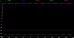
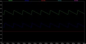
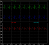
agdr, I did a side-by-side simulation of your original schematic (top), and a modified version (bottom). The modification added four new components; they are marked with red stars. Simulation results show the same average DC voltage on the "Vin2" rail, but quite a bit less ripple.
If the LT1963A attenuates ripple by 560X (55 dB on the datasheet), then less ripple on the input means less ripple on the output. OutputRipple= (SMALL / 560) is less than OutputRipple= (BIG / 560), it seems to me.
Indeed why not place a similar attenuator into the other, negative, leg of the supply as well?
Attachments

I've used the Jung regulators with X7R 0.1uF ceramic bypass caps at the load and have not experienced any oscillation. One such example is my modded up Adcom GFP-565 preamp (a la Galo's thoughts from AX a few years ago.)
If you put a a film cap on the output of the Jung regulator it "may" oscillate. If you put a ceramic cap right at the opamp it most likely will not oscillate. There is inductance and resistance of about 10nH/cm 40mR/cm which decouple the regulator a bit.
How long is the wire between the output of your reg to your bypass cap? Did you use remote sensing?
If you're going to DIY a Jung regulator, I would pay close attention to the layout of Jan's implementation in part 3. This is a very high gain, broadband circuit and the layout was carefully designed to take this into account. Unfortunately, the Old Colony boards are no longer available, but the template can be found archived on Walt's website.
I have built the Iko reg and Salas reg and they sound pretty good if implemented properly. The negative point about all shunt regs is that they require very large heatsink therefore are less practical to build. Since I have a 4 way active crossover which requires 4 regulators, and out of which the tweeter branch is the most important, if I can't find anything sonically better I may still opt for a shunt for the tweeter branch, but would be happy to use series regulators for the midrange to subwoofer. I have no doubt that the Jung reg would be best for the midrange and bass. Perhaps I should build it again with optimal layout and see if it fits for the tweeter branch. I used dot matrix board to build it last time and this time perhaps I would design a two layer board using expressPCB. Now I have to go back to those threads and spend a couple of weeks reading them for the second time.
Could you post a link to the picture of the optimal old Colony board layout?
The regulators which just stood out above all else were the Jung, Sjostrom, Burson, NCD and Linear Tech LT1963A/LT3015. They were in a class all by themselves. The LM317/337 were near the bottom, along with the Bybee Music Rail (not a regulator btw) and Super-Teddy. The latter 3 were not neutral, they interfered with the musical presentation.
Thanks for your valuable subjective evaluation report and I take it seriesly. From your measured data, it is unbelivable that the Burson reg could sound good, as it measured 10 times worse than the humble LM317/337. I built the LM317/337 no less than 6-7 times in the past 10 years and I did not like the sound for the first 5-6 times, but the last build did give quite good sound.
Is the Sjostrom' a derivation from the Jung reg? I have not found any information on that one.
Last edited:
- Status
- Not open for further replies.
- Home
- Amplifiers
- Power Supplies
- Modern 317/337 alternatives?