
D
Deleted member 148505
i creat IRS 900-1500-2000-3000
i was use IC TC4049
no one worked 🙁
Use Texas Instruments CD4049UBE. I created my own layout based on IRS900 and it worked the first time.
Hi Raj,
use BAL IN for input or you can use as unbalanced mode
UN Balanced Mode:
(+) sign connected to GND(marking shows wrongly)
(-) sign as input with respect to GND
Regards
MANOJ
Hi Manoj:
I tried as you mentioned, given input to both -+ points one after another with respect to gnd. Still no sound from Spk.
But if I connect Pin-2 (tl072) to gnd through 220n or resistors like 1K then I get output.
Managed to prepare output inductor as per your instruction. Improved a bit, I used EE cores 24turns 19SWG wire. How many turns for emi reduction coil?
Thanks
Raj
schematic and pcb can not work without aplication program
PT2322 project near the end
i replace new ic with PT soon
when complete the project i share that with you friend.
what about AUD600 ?
compelet that ?
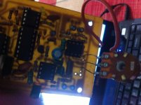
Hi Hadi/Manoj/Stewin:
I completed aud600 ver1.0 it works but has some problems. Now trying to solve them
1. If I give audio input to - or + sign with respect to gnd (giving any -/+ to gnd) then there is no output until I give gnd through cap/resistor to pin 2 of tk072 then I get output. Why?
2. My 47ohms resistors are burning instantly, HF is too high but how to control that?
3. I get choppy sound at higher volume.
NB: resistors in pic burned (value is ok) when I used them in 47ohms position.
Have you faced any of such problem? And how you fixed that?
Attachments

Last edited:
Hi dear friend
Hi friend
is this an amp ?🙂
some time we must wait and try long time. when we wait for along time we can find beter way for our problem.
dont be tierd friend and try more and more. you can do any thing if you want.
best wishes for you friend
Hi Hadi/Manoj/Stewin:
I completed aud600 ver1.0 it works but has some problems. Now trying to solve them
1. If I give audio input to - or + sign with respect to gnd (giving any -/+ to gnd) then there is no output until I give gnd through cap/resistor to pin 2 of tk072 then I get output. Why?
2. My 47ohms resistors are burning instantly, HF is too high but how to control that?
3. I get choppy sound at higher volume.
NB: resistors in pic burned (value is ok) when I used them in 47ohms position.
Have you faced any of such problem? And how you fixed that?
Hi friend
is this an amp ?🙂
some time we must wait and try long time. when we wait for along time we can find beter way for our problem.
dont be tierd friend and try more and more. you can do any thing if you want.
best wishes for you friend
thanks friend
pinout is same
what is the problem ?
i dont know
thanks for your helping🙂
i was download data sheet for TC and CD icsUse Texas Instruments CD4049UBE. I created my own layout based on IRS900 and it worked the first time.
pinout is same
what is the problem ?
i dont know
thanks for your helping🙂
1. If I give audio input to - or + sign with respect to gnd (giving any -/+ to gnd) then there is no output until I give gnd through cap/resistor to pin 2 of tk072 then I get output. Why?
Hi Raj,
VOLUME control(100K or 50K) side pin connected to 33K resistor from Pin-7 of TL072, center pin from Pin-2 of TL072 and another side from Pin-1 of TL072.
Regards
MANOJ
Hi Raj,
VOLUME control(100K or 50K) side pin connected to 33K resistor from Pin-7 of TL072, center pin from Pin-2 of TL072 and another side from Pin-1 of TL072.
Regards
MANOJ
Hi Manoj: Volume is 100K. Connected as per diagram you given. Will recheck to confirm.
How many turns for emi reduction coil?
Thanks
Raj
2. My 47ohms resistors are burning instantly, HF is too high but how to control that?
Hi Raj,
your VOLUME control wiring is wrong b'cause of that open loop gain effected in TL072 pin-1, so that HF is too high.
Regards
MANOJ
How many turns for emi reduction coil?
Hi Raj,
for first setup do not use EMI reduction winding.after everything working perfectly then use. it should be 10 Turns
Regards
MANOJ
Hi Raj,
check my connection picture again for VOLUME control wiring
Regards
MANOJ
check my connection picture again for VOLUME control wiring
Regards
MANOJ
Last edited:
My New PCB , IRS-2000D , will be IRS-3000D if used +/-130V 😀 .
🙂 Good evening.
This pcb is correct?
I'm intending to build this amp.
You have to send me the files?
Thank you.
luizcpimenta@yahoo.com.br
luizcpimenta@gmail.com
My new layout for 1KW Class D with onboard OCP and onboard bias supply. 🙂
2 Pairs IRFB4227 TO-220
Hi jlester
did you test your pcb ?
is that worked ?
can you send to me yor pcb file please ?
thanks
Hi Raj,
VOLUME control(100K or 50K) side pin connected to 33K resistor from Pin-7 of TL072, center pin from Pin-2 of TL072 and another side from Pin-1 of TL072.
Regards
MANOJ
Hi Manoj: I think my wiring is as per your diagram/instruction. Attacing a picture for better understanding, is it okay.
Thanks
Raj
Attachments
My new layout for 1KW Class D with onboard OCP and onboard bias supply. 🙂
2 Pairs IRFB4227 TO-220
Good afternoon.
This layout worked OK?
Its send me the files?
luizcpimenta@yahoo.com.br
luizcpimenta@gmail.com.
Thankful.
Hi Raj,
for first setup do not use EMI reduction winding.after everything working perfectly then use. it should be 10 Turns
Regards
MANOJ
the 10turns should be winded on what type of material?
- Home
- Amplifiers
- Class D
- UCD 25 watts to 1200 watts using 2 mosfets