Thank you, Lazy Cat and Alex MM. Alex, may I have a pdf of the bottom copper side of the VSSA PCB using the ALF08NP16V5 ?
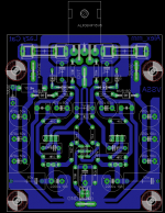
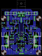
Credit to Alex_mm just add the zobel network and solderpad for trimmer during fine tune session. Board has exact same size as Alex ones.
10uf MKT are Vishay Roederstein ref : MKT1820610065
470uF 50V are panasonic Fc
2200uF 10V are panasonic Fr
Marc
10uf MKT are Vishay Roederstein ref : MKT1820610065
470uF 50V are panasonic Fc
2200uF 10V are panasonic Fr
Marc
Attachments
Last edited:
Should we put some realistic values into play??
I have adjusted the ltspice simulation file.
I have adjusted the ltspice simulation file.
- First of all the bias is set to ~370mA instead of 2A=> 26Watt idle instead of 140Watt idle!
- Miller caps is adjust to 56pF instead of 22pF -> stable into 1uF||8R - before not even stable into 100nF||8R
- THD at 20KHz 20Vp is now 0.04% into 8R.
- THD at 1KHz 20Vp is now 0.002% into 8R
- The output impedance is not negative but .2mOhm. Very good but not negative
Attachments
-
vssa updated op.txt2.1 KB · Views: 206
-
ecf10n20.zip2.6 KB · Views: 237
-
vssa updated 1k thd.txt2 KB · Views: 231
-
vssa updated 1k.pdf81.8 KB · Views: 317
-
vssa updated 20k thd.txt2.1 KB · Views: 167
-
vssa updated 20k.pdf186.7 KB · Views: 282
-
vssa updated freq response.pdf119.1 KB · Views: 246
-
models ksc3502 ksa1381.txt695 bytes · Views: 269
-
vssa updated.asc6.3 KB · Views: 213
-
vssa updated sch.pdf13 KB · Views: 546
Should we put some realistic values into play??
Realistic hehe, cannot go more realistic than my real measurements. See how models differ from reality, examplary case here.
I can assure you'll get the same results if you'll assemble VSSA and use the same BOM as I did. 😉
Regards Andrej

P.S. Miller caps are 12 pF SMDs and VSSA is completely stable.

Last edited:
Feedback Resistors
Will it be useful to make provision for parallel resistors (R5 or R6) for the feed back for finetuning? Should be more easy than 0.1% tolarence resistors.
Credit to Alex_mm just add the zobel network and solderpad for trimmer during fine tune session.
Marc
Will it be useful to make provision for parallel resistors (R5 or R6) for the feed back for finetuning? Should be more easy than 0.1% tolarence resistors.
Last edited:
Realistic hehe, cannot go more realistic than my real measurements. See how models differ from reality, examplary case here.
I can assure you'll get the same results if you'll assemble VSSA and use the same BOM as I did. 😉
Regards Andrej
P.S. Miller caps are 12 pF SMDs and VSSA is completely stable.
Maybe it is stable on your table. he he 😀
No serious. I am not joking.
The TSSA needs a 47pF to be stable and has a "shorter path". This is also stable on the bench with 22pF , but not connected speaker cables and speakers. Some times you could hear it, other times it just run hot very fast.
The mosfet has not secondary breakdown, but high current/power disipation will shorten there life cycle.
it is a matter of believe.: I will always design an amp to the safe side. But if you think it is okay to balance on the top of the mountain, i have no problem with that.
Now i have said what i mean is necessary. 😉
this is my finding too, 56pF is better47pF to be stable
happy new year!

Maybe it is stable on your table. he he 😀
No serious. I am not joking.
The TSSA needs a 47pF to be stable and has a "shorter path". This is also stable on the bench with 22pF , but not connected speaker cables and speakers. Some times you could hear it, other times it just run hot very fast.
The mosfet has not secondary breakdown, but high current/power disipation will shorten there life cycle.
it is a matter of believe.: I will always design an amp to the safe side. But if you think it is okay to balance on the top of the mountain, i have no problem with that.
Now i have said what i mean is necessary. 😉
Hello
Thank you for these very valuable information!
I work with these topology more than 20 years. All do I used power darlingtons not lat. FET I run into the same problem (sometimes).
(The main reason I needed to use different type of darlington because Texas Isnt. stopped produce those transistors the amp was design)
The amp sounded excellent and look like works perfect after a while (less than one hour)the power darlington just blew up.
The bias was way to low (50mA) to say that caused these problem and the PSU voltage was OK to.
The funny thing the same time I switched to a other type of darlington which almost half the power of the previous blew up darlington and that worked with out no problem..
Now I will test the amp with Hitachi lat. FET to.
I did not hock up the amp to the scope (I do not own one). Still good to know these topology need these comp. or Miller capacitors.
Is it better to use it on the VAS or the power FET or transistor? Sorry if these question sound a bit stupid..
Someone advised to use the caps on the power stage😉 that is why I ask.
Do these capacitor will degrade or effect the sound in a negative way?
Greetings Gabor
Do these capacitor will degrade or effect the sound in a negative way?
sounds like they have more positive effect than negative 😉😀
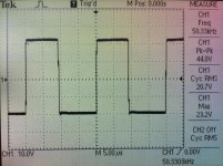
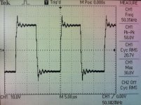
VSSA measurements, +/- 32 V rails
1.pic - 50 kHz square wave, 20,7 Vrms/8 ohm, 2,5 Arms
2.pic - the same as first only 0,22 uF parallel to 8 ohm load
Not bad for six transistors amplifier with no CCS.
1.pic - 50 kHz square wave, 20,7 Vrms/8 ohm, 2,5 Arms
2.pic - the same as first only 0,22 uF parallel to 8 ohm load
Not bad for six transistors amplifier with no CCS.
Attachments
Last edited:
P.S. Miller caps are 12 pF SMDs and VSSA is completely stable.
Hi LC, are you using classical NPO smd brand for miller cap?
Marc
RF quality SMD capacitors. Copper heatsink is in electrical connection to sources of ALF, so a little portion of capacitance coming from here is in addition to Miller cap too.
I'll try to replace injection resistors with CCS to see possible improvement in the next test.
Regards L.C.
I'll try to replace injection resistors with CCS to see possible improvement in the next test.
Regards L.C.
RF quality SMD capacitors. Copper heatsink is in electrical connection to sources of ALF, so a little portion of capacitance coming from here is in addition to Miller cap too.
Thanks, what do you mean by copper heatsink?
Marc
LC one more question : in his layout Alex swap the 1000uf 50v implicated in first stage power supply to 470uf 50V is that sufficient to your taste?
Marc
Marc
You could hack this amp.
http://www.diyaudio.com/forums/soli...-gain-mosfet-output-stage-11.html#post3213913
Use the output stage (M1, M2), the buffer which makes the mosfet switch fast (Q15,Q18 R4,C1,R21,R13,R14), use the VAS (Q7,Q6,Q5,C3,C4,Q8,Q9,Q10,R5 - R8)
Q5,Q8,Q15,Q18 can easily be DZT5401,DZT5551.
The general bias in this amp is very low. V4 can be a trim resistor with 47uF in parallel. Or as Lazycat TL431.
We are down to 4 - 8W per channel from +/-35VDC supply.
The use the frontend of the VSSA.
C3 and C4 is in reallife 47pF each.
two CRDs instead the 470ohm resistors (input pair's collector to rail), improve THD by 30%, mostly 2nd order.
You could hack this amp.
What do you mean? To combine two amps? Please elaborate Sonny. 🙄
At VSSA we are fixed to six transistors only, as promised.
- Home
- Vendor's Bazaar
- VSSA Lateral MosFet Amplifier