Hi Forsman,
I like the styrofoam, easy to cut and shape. Old newspaper scraps (or Raufasertapete?) soaked in wallpaper paste should reinforce the surface just fine.
Regards,
I like the styrofoam, easy to cut and shape. Old newspaper scraps (or Raufasertapete?) soaked in wallpaper paste should reinforce the surface just fine.
Regards,
I think you do. 😀Do I think what you think? In that case I'm not sure it will work. The density/stiffness of the styrofoam doesn't look 'experimental correction' enough....🙂
And I have the same doubt about the stiffness of the material.
That I dont know. It is the cheapest sort made for insulation in construction works.Is it expanded or extruded polystyrene?
Could be an option but I am trying to find a simpler solution.Fibreglassing over foam?
That might be the simpler solution I am looking for. 🙂Old newspaper scraps (or Raufasertapete?) soaked in wallpaper paste should reinforce the surface just fine.
/Forsman
The usual Polyester resin used in "fiberglass" eats Styrofoam in seconds 😱.Fiberglassing over Styrofoam ?
Could be an option but I am trying to find a simpler solution.
/Forsman
Boat and surfboard manufacturers use a special foam and epoxy, as did Sound Image for their speaker cabinets.
Very light, very stiff, very expensive 😉.
- Thanks for the warning. 🙂
That’s one reason to try a simpler way of creating a hard surface in an easier manner. I have thought of Divinycell and/or Epoxy but Epoxy is pretty toxic and thus a bit hard to work with. I occasionally use both Polystyrene and Epoxy to mend boats but for this trial I need a simple way of creating a cone volume compensation that is just good enough. Maybe it will suffice with Raufasertapete or even just a layer of paint, at least at low volume.
/Forsman
Last edited:
Maybe wood is an idea...........try a simpler way of creating a hard surface........Epoxy..... toxic........hard to work with......... I need a simple way of creating a cone volume compensation.......
 It's hard by itself, it takes 10 minutes to make 3 shapes and voilá........😉
Polystyrene and epoxy are compatible. Oh and extruded is stronger than expanded.
good luck.
-Matt
good luck.
-Matt
I haven’t been able to compensate for cone volume yet but I do have tried with some damping at 170 cm from S1 with promising result.
Measurement at mouth. Horn placed in a corner in a large open floor. 6 db/oct smoothing.
/Forsman
Measurement at mouth. Horn placed in a corner in a large open floor. 6 db/oct smoothing.
An externally hosted image should be here but it was not working when we last tested it.
/Forsman
/Forsman
So call me lazy, but what's the internal width of the cabinet? It looks like there's a lot of space on either side of the driver.
tnx,
gs
I believe now the esteemed Mr. McBean has added Vtc and Ap1, so there is definitely a model for the cone volume. Theres now even a very friendly wizard to calculate how much volume your cone uses.
Hi Forsman,
Sorry I didn't reply earlier but (enough) time is sometimes difficult to find...😱
To be honest I think (just my opinion) that using Resonators/absorbing techniques only increases losses. I prefer to optimise the design rather than creating more losses. To me your 'dip problem' is the result of the difference between sim and design, like I stated earlier. I think it would be helpful to have a more accurate model to see what’s going on. It also help me 🙂 to explain what I meant with the cone volume correction.
The volume within the cone is usually the main reason why the dip is (usually) larger in measurements compared to the sim. In other words the volume at S2 in the original model doesn’t represent the volume in reality. In my post#23 of the "SS15 or Tham 15?" thread I showed an example of an alternative way of simming the THAM. The alternative model shows the dip pretty accurate and looks similar to what one can measure from a standard Tham.
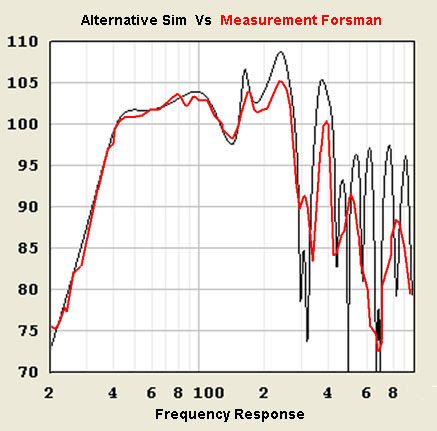
To make such alternative sim for your Thorn F1, I used your measurements to go from. First, I implied your measurement within the graphic ratio of HornResp. This gives a much easier comparison tool between model and measurement. After that I made some small changes in the HornResp input parameters to correct the volume at S2 and S4 and some small changes for the correct position of the point source ( lays within the cone). When you increase the volume at S2 one needs to compensate at S4 in order to keep the correct total internal volume of the enclosure. By using the exact frequency location of the peaks and dips of your measurements I tried to improve the model further. In the next picture you see the result (black) in combination with your actual measurement (red), all in the same plot ratio.
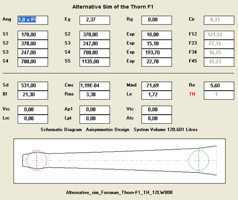
The input page looks like this:
Now you have an more accurate model you can see that by making the S2 area smaller (Cone Volume Correction) you can optimise the model to what you have modelled in the first place. I did so by decreasing the volume of S2:
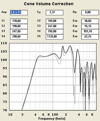
This example of the cone volume correction should bring it back to what you have simmed (freqeuncy response) in your original model. What this Cone Volume Correction will do is increase the compression at S2. Therefore the pressure minimums at S2, those of the 1/2 wavelength and full wavelength, will rise.
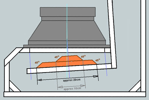
If you decide to experiment with the cone correction I made a quick sketch of how to start. You can experiment with smaller and larger shapes until you find the best solution.
- Status
- Not open for further replies.
- Home
- Loudspeakers
- Subwoofers
- Thorn F1 - a learning experiance with Tapped Horn