Hi,
Some links below. Zaphs site is the best for explicitly showing
the difference between electrical and acoustic x/o functions.
e.g. Zaph|Audio
Is 4th order L/R acoustic at 2KHz, but due to the drivers and
the box the electrical x/o function is nothing like 4th order L/R.
Treble is 2nd order and mid bass third order elliptical (Cauer).
For the Cauer the 1st order part incorporates BSC and the
carefully dimensioned following 2nd order notch suppresses
the drivers peak whilst also emulating the L/R roll-off.
Result ? something near 4th order L/R acoustic, assymetric due to the forward tweeter :
(The on purpose assymetry realigns the optimum listening axis not to be down tilted.)
Zaph knows his stuff 😉.
rgds, sreten.
http://sites.google.com/site/undefinition/diy (see if nothing else, the excellent FAQs)
http://techtalk.parts-express.com/sh...d.php?t=219617
Zaph|Audio
Zaph|Audio - ZA5 Speaker Designs with ZA14W08 woofer and Vifa DQ25SC16-04 tweeter
FRD Consortium tools guide
http://web.archive.org/web/200909021...esigningXO.htm
RJB Audio Projects
http://web.archive.org/web/200909022...ve99/Spkrbldg/
Speaker Design Works
http://www.htguide.com/forum/showthread.php4?t=28655
A Speaker project
http://www.troelsgravesen.dk/Diy_Lou...r_Projects.htm
Humble Homemade Hifi
Quarter Wavelength Loudspeaker Design
Pi Speakers - unmatched quality and state-of-the-art performance
The Frugal-Horns Site -- High Performance, Low Cost DIY Horn Designs
6.283 Audio Pages
Linkwitz Lab - Loudspeaker Design
Music and Design
Great free SPICE Emulator : http://focus.ti.com/docs/toolsw/fold...t/tina-ti.html
Last edited:
Awesome! Much appreciated, sreten !!!!
I will minutely go through them and post my queries here, if any!
Thanks a ton!
I will minutely go through them and post my queries here, if any!
Thanks a ton!
Last edited:
this link http://www.troelsgravesen.dk/Diy_Lou...r_Projects.htm
is not working I guess. Could you kindly check it ? 🙂
is not working I guess. Could you kindly check it ? 🙂
I have another quick question.
If I switch to open baffle design, could these practical problems be minimized ?
If I switch to open baffle design, could these practical problems be minimized ?
DIY Loudspeakers
Hi,
The above should work for TG's site.
Open baffle design causes even more misunderstandings and mistakes
IMO, and certainly doesn't minimise any problems of doing it right IMO.
Having said that, I like : https://sites.google.com/site/undefinition/diy-sunflowers
rgds, sreten.
Hi,
The above should work for TG's site.
Open baffle design causes even more misunderstandings and mistakes
IMO, and certainly doesn't minimise any problems of doing it right IMO.
Having said that, I like : https://sites.google.com/site/undefinition/diy-sunflowers
rgds, sreten.
Last edited:
Now the link is working!
Thank you sreten for your inputs regarding my misconstrued thinking related to open baffle design as I read somewhere earlier that they are considered as the ultimate solution in speaker design technology!
Thank you sreten for your inputs regarding my misconstrued thinking related to open baffle design as I read somewhere earlier that they are considered as the ultimate solution in speaker design technology!
Hi,
Nothing wrong with good OB designs if that is what you want and
you understand the SPL limitations regarding bass driver size.
They are more difficult to design properly than box speakers IMO.
(Though they can be far easier to build.)
See the MJK, Linkwitz and M&D sites.
rgds, sreten.
Nothing wrong with good OB designs if that is what you want and
you understand the SPL limitations regarding bass driver size.
They are more difficult to design properly than box speakers IMO.
(Though they can be far easier to build.)
See the MJK, Linkwitz and M&D sites.
rgds, sreten.
Last edited:
Another question.
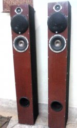
Can I use a full range 3 way car speaker as mid range ( adjusting level ofcourse) along with a midbass and tweeter in a 3 way system?
Is this a pragmatic implementation?
For the time being I added two Car Speakers in the middle for experiment . (The black ones in the photo)
Can I use a full range 3 way car speaker as mid range ( adjusting level ofcourse) along with a midbass and tweeter in a 3 way system?
Is this a pragmatic implementation?
For the time being I added two Car Speakers in the middle for experiment . (The black ones in the photo)
Attachments
Last edited:
In my situation, which one would be better, could you please suggest ?
1. Using the full range for lowpass filter, omitting the current mid-bass
or
Using the mid-bass only ( ignoring the car speakers )
1. Using the full range for lowpass filter, omitting the current mid-bass
or
Using the mid-bass only ( ignoring the car speakers )
So sorry.
1. The full range is from Rockford ( Model R1653)
3 Way, 48-22kHz,
Voice coil diameter= 1.25(3.23)
Free Air Resonance = 67
Qts = 0.78
Vas-cu.ft.= 0.53
SPL ( db@1w/1m)89
Power Handling Watts ( RMS) 40, peak = 80
2. No specific data available about the midbass except its a 8 Ohm , 6.5 inches midbass
3. Tweeters 4 Ohms paper cone
Hi,
The car speakers belong in a car. Can't say much about the other drivers.
Car drivers hardly ever cut the mustard for home hifi use, they are poor.
rgds, sreten.
The car speakers belong in a car. Can't say much about the other drivers.
Car drivers hardly ever cut the mustard for home hifi use, they are poor.
rgds, sreten.
Last edited:
Earlier I used the car speakers with my discrete Mosfet Amp. I noticed one thing in my small listening room.
They are good in a very near field listening environment but they tend to lose focus or their sound doesn't spread well . ( trying desperately, using my layman's term, hehe)
I will experiment more and post my observation.
Thank you again sreten.
They are good in a very near field listening environment but they tend to lose focus or their sound doesn't spread well . ( trying desperately, using my layman's term, hehe)
I will experiment more and post my observation.
Thank you again sreten.
I had used same toner transfer paper method for pcb making. I was also not very certain about the result but it was very good.You go ahead with a good dark laser print on the magazine paper and follow the method..surely you will get good result..Thank you really so much Sudhir for your kind advice. I consider your this post as an encouragement.
Sometimes we face problem due to a slight inadvertent mistake in the PCB design posted on the internet . But your words really helped me to get rid of that concern.
Could you please tell me how you made the PCB ? I am a bit hesitant to use my old toner transfer method in this case as the board is large and fairly complex.
( Oh, I purchased 6 TLO74 Ics and sockets and some 1% metal resistors. And some other parts are already in my inventory. So wish me luck please 🙂 )
thanks
sudhir.
Thank you so much again Sudhir .
I am trying to create a top layer too for component reference with Gimp. Let's see how it goes.
I will post photos of my works here soon.
I am trying to create a top layer too for component reference with Gimp. Let's see how it goes.
I will post photos of my works here soon.
.....................You go ahead with a good dark laser print on the magazine paper and follow the method..surely you will get good result..
thanks
sudhir.
I have 2 questions here.
1. Very soon I am planning to buy a laser printer that is low cost, low maintenance, and suitable for my DIY PCB making.
Which Laser Printer do you recommend ?
2. At present I use laser tracing paper but I heard many good things about magazine paper on the net. But I am confused which Magazine ( or type of paper ) to use as there are many types of magazines available in India as you are well aware of and they use different types of paper .
Could you name a magazine that can be used for this purpose?
Thank you.
Another question 🙂
How did you get the component reference on top layer on the PCB that you made as the photo of the top layer is not identical in size with the PDF of the copper layer?
Did you use a paper print and stick it on top?
I used Gimp to adjust the top layer coordination with the copper side but couldn't be able to get the correct size at first.
I somehow managed that finally.
Another question 🙂
How did you get the component reference on top layer on the PCB that you made as the photo of the top layer is not identical in size with the PDF of the copper layer?
Did you use a paper print and stick it on top?
I used Gimp to adjust the top layer coordination with the copper side but couldn't be able to get the correct size at first.
I somehow managed that finally.
@csom,
I have the PCB and components left out with me. If you are interested please let me know. You can reach me at bibin3210atgmaildotcom.
Thanks,
Bibin
My previous post is lost perhaps because of Internet problem.
So I am posting it again.
Thank you so much bibin.
Much appreciated.
I made 3 layers ( top, bottom, drill hole ref ) from the download of that site, and gave it to a man who makes PCBs. Probably he is going to charge me a fortune but since this Project is well tested by our respected fellow members like Pra, Sudhir and many others, I decided to take the risk.
I might get the PCB the day after tomorrow if everything goes well.
If not, I definitely will take resort to your kind concern.
Thanks a lot, really, Bibin,
Last edited:
- Status
- Not open for further replies.
- Home
- Source & Line
- Analog Line Level
- DIY 3 way active crossover: as Christmas Holiday Project