Hi Everyone,
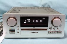
My old Bose Wave Radio, Model AWR1- 1W, recently stopped working.
At first it wouldn't power up at all. I got hold of the service manual and guessed, correctly, that a likely cause was the R6 resistor. I replaced it and that fixed the power up issue but it remains with no sound. All the displays are OK - stations, volume, clock etc. just no sound.
If you know how to fix or troubleshoot this problem I would appreciate hearing from you.
I've just joined diyaudio on a friend's suggestion. Also checked previous posts and haven't found any relevant info.
thank you.
Yep, we need to see the circuit details.
You have to check the basics... are all supplies present and correct and reaching their destination.
You have to check the basics... are all supplies present and correct and reaching their destination.
When they are located on the wifey's side table and stop making music, things are not at their best...
about
http://www.diyaudio.com/forums/soli...d-gallery-inside-devices-serv-man-wanted.html
I ask for a schematic.
Observe this thread.
Additional you can call there for a schematic:
http://www.myboserepair.com/bose_wave_radio_repair.htm
and
http://stores.ebay.com/OnbudgetRadio?_trksid=p4340.l2563
or a member from far east can ask there for a schematic:
http://nyatampo.at.webry.info/200812/article_2.html
and perhaps this help:
http://911manuals.com/product_info.php/products_id/226506
http://911manuals.com/product_info.php/products_id/226515
http://www.geek.com/hwswrev/conel/tabrads/index.htm
Last edited:
My bose aw1 radio also arrived DOA, but @ $5 I wont complain and the wife has wanted one for 20 years. Ergo I fix this one and give it to her as a B'day present if only to prove her wrong ... OK fine that's the beer talking ... OK.
Now I have the manual, except I cant edit it, and I cant post just the schematic.
Has anyone fixed this issue in a bose wave radio - no display and no sound - except for a faint hiss when plugged in and a light pop when unplugging, and none of the buttons on top, on/off, volume, channel up/down etc etc has no effect.
I will post a schematic as soon as I figure how.
Cool.
Srinath.
Bose in similar Outline than Accuphase/Luxman
Are the models PLS1310 and PLS1510 only produced for the marked in Japan?
BOSE PLS-1310‚ÌŽd—l ƒ{�[ƒY
InJapan.ru ? *BOSE*WestBorough CD ??????? PLS-1310 ????????, ???????? ? ???????? ???? ** ? ???????? ????
For service on older Bose devices for Europe and USA this ebay members are of interest:
BOSE AMPLIFIER REBUILD SERVICES | eBay
Bose 800 802 901 Equalizer Repair Service Capacitor Replacement & Upgrades | eBay
Bose Wave Radio CD, Service Manual in PDF format | eBay
REPAIR SERVICE for Bose Wave Radio/CD system AWRC-1P | eBay
Attachments

Last edited:
I have a unit with the same problem. No display or functions but you can hear the audio amp glitch when you unplug it . Did anyone come up with the fix?
locked88
locked88
No display or functions suggests to me that it might be a digital problem, ie a processor is kaput. Have you tried injecting a signal to the analog section?
Just guessing... I've only seen these things in the ubiquitous advertisements.
Just guessing... I've only seen these things in the ubiquitous advertisements.
Did that
I did, still not make sound.
I'll look into that "myboserepair" page.
Cool.
Srinath.
No display or functions suggests to me that it might be a digital problem, ie a processor is kaput. Have you tried injecting a signal to the analog section?
Just guessing... I've only seen these things in the ubiquitous advertisements.
I did, still not make sound.
I'll look into that "myboserepair" page.
Cool.
Srinath.
Myboserepair is a repair store, I didn;t ask there, they obviously are into repairing these professionaly. I am not that certain I wanna spend 99 bucks and 2 way shipping to fix this bugger, I have other clock radio's I can use.
Cool.
Srinath.
Cool.
Srinath.
fixing
Some people must know the fix for these as even the non-working models are selling for a ridiculous price on eBay. I wanted to pick up a dead one, for a few bucks, so I could gut the electronics and hook up a T-Amp board I had laying around, just for fun.
I know, I’ve got way too much time on my hands.
.
.
.
Last edited:
I had (have?) the same problem...Mine's a Series 2 Wave Radio, 3 AAA batts for standby. The battery contacts were clean, no leakage. I put in new Energizer alkalines that worked fine for maybe 2 weeks, then the display and functions petered out dead again. Just now replaced with Duracell alkalines, and it came back to life again, for how long I don't know. Will post again if and when it dies.I have a unit with the same problem. No display or functions but you can hear the audio amp glitch when you unplug it . Did anyone come up with the fix?
locked88
Thanks,
Ears2U
Bose Wave Radio 1996 Model
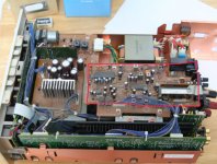
Replace Q1 or do what I did much better solution.
Q1 dies it is a 2SC1394 or similar NPN 1 watt transistor.
When it shorts out however it takes 2 resistors with it. Its a voltage splitter off the 10V regulator, so it creates 5V to run the set.
Since the resistors are surface mount, and its a pain to remove them and replace, here is a much cheaper solution.
Find a used Cell Phone wall wart charger. Dis assemble it, and inside is a small circuit board, with leads going to the 110V ac plug. Cut the leads off the AC plug, cut the wires leave 3-4 inches or so, use to wire the 5V output in place of Q1. Q1 is located next to the bridge rectifier. you need to remove it. Wire the red +5v wire from the cell phone pcb, to the hole closest to the rear of the radio. (Hole located toward heat sink). Or you can also wire it to Pin 15/16 of IC601 to any point in the set that the 5V is present.
I then wrapped the wall wart board in insulating cardboard, paper or just use Gorilla Tape and wrap it up good so it will not short out (ever). Mine had an LED I let that stick out to indicate it is working.
I then stuck it between the transformer and the heat sink, you could hot glue it into place if you wanted. I then wired the 119V leads to the bottom of the AC pins where the transformer (2 pin plug) goes to supply 110v to the wall wart charger board). reassemble making sure nothing is forced into place.
Now here is a link to the PDF file if you want to try to just fix it using the normal parts. Bose WaveRadio1996 Service Manual free download,schematics,datasheets,eeprom bins,pcb,repair info for test equipment and electronics
In that same site is all the BOSE schematics for all the Bose products.
Here is what I find too funny. I called Bose before I discovered the schematic and asked them where to get a schematic.
They said, OH that is HIGHLY CONFIDENTIAL information and not available to the public. Instead he offered to sell me a newer model at a much reduced cost. Not interested. $150 is a bit too steep for a clock radio, no matter that it sounds great.
(Even though it does have a CD player in it).
I almost want to call them back and explain that the information is online.
Another probably much more effective way, would be to replace the Q1 with an LM7805 Positive voltage regulator. Wire left pin to the Center pin of Q1 (Collector) which is 20V but passed thru 50 ohm resistor, wire right pin to the same pin facing to rear of the set toward heat sink which is 5V output, and wire the center pin ground to any closest ground point. I would solder to one of the shield cans. Or the bridge rectifier pin that is ground I think but check with ohm meter is the pin closest also to the rear of the set. Insulate or isolate the LM7805 IC to prevent shorting anything in the set.
I would go this route as it is an obvious weak link in this set.
kb50
Could you maybe post a photo of this? (the method you tried) I have the same problem with mine. No power but it makes static noise when you unplug the unit.
Could you maybe post a photo of this? (the method you tried) I have the same problem with mine. No power but it makes static noise when you unplug the unit.
For anyone who stumbles upon this thread, I had the same problem with my Bose wave radio as described by the OP. The radio was completely dead but it would make a static noise when you unplugged it. After some research from this thread and many others I did some testing and found that my Q4 transistor had shorted. I guess this is a common problem for these units. The Q4 transistor 2SC3792 is under built and shorts between the emitter and the base. You can test this with your multimeter between the two outside pins. If you read anything around 0-3 Ohms you have a short. Bose recommends a replacement part and you can look that up if you want but it’s difficult to find. I used a 2SC2655 and my problem was solved. I’m not saying this is the only thing that could be wrong with your unit but it’s easy enough to test.
- Home
- Amplifiers
- Solid State
- Anyone fixed a Bose Wave Radio with no sound?