I found C2 (the 150pf) could be safely omitted but I would still advise as a generalisation to keep it. It's a low pass filter and will ensure absolute stability and kill any RF that might find its way into the amp... things that depend on individual circumstances.
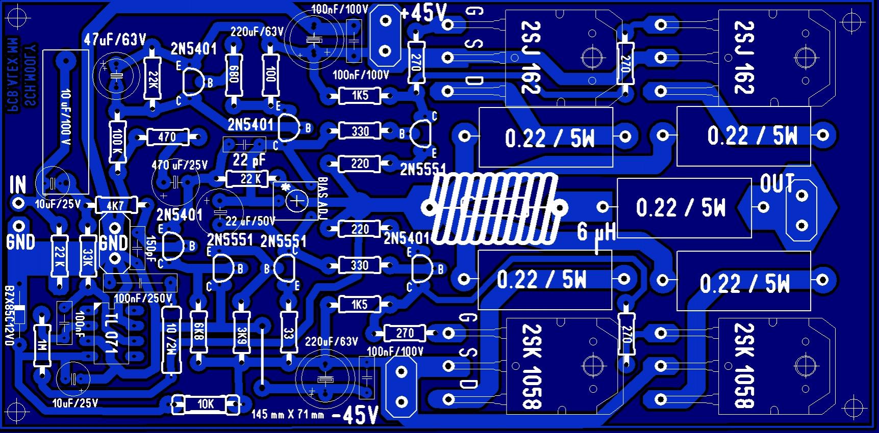
Alexs' PCB looks brilliant to me although there is one error if you look at the "top 2N5401". The base and emitter are joined 🙂
I'm hopefully going to index the original thread (the first post) to link to the important points on the build.
Alexs' PCB looks brilliant to me although there is one error if you look at the "top 2N5401". The base and emitter are joined 🙂
I'm hopefully going to index the original thread (the first post) to link to the important points on the build.
So far the best amp class A/B that I have heard and still in my living room is the M400.I compared side by side with Bryston B60 and the M400 is a superior amp not only in power but in sound 😉 2sk1058 2sk2221 irfp9240 mosfet amplifier schematic
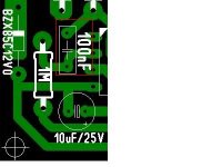
Mooly, C8 (0.1 uF) is an electrolytic condensador?
No, its just a normal poly/film type like this,
B32520-C3104-K - EPCOS - CAPACITOR, B3252 0.1UF 250V | CPC
lanchile: Do you have the schema?
Sorry, I do not have it, you can order a module and try. all what is said about it on their web is true!. the board is top quality (made in USA). all parts are original and high quality. I have build so far five amps using these M400 for family and close friends and one T300, but I like the M400 better. They are fantastic 😉
I've started an index on the original thread post #1,
http://www.diyaudio.com/forums/solid-state/119151-my-mosfet-amplifier-designed-music.html
http://www.diyaudio.com/forums/solid-state/119151-my-mosfet-amplifier-designed-music.html
Hi mooly, i'm finishing the pcb, but i have one doubt, What is the function of r26?
Although it is a low value (only 0222 ohms) i do not understand the reason that is placed in series with the speaker.
Thank very much!!!!
Although it is a low value (only 0222 ohms) i do not understand the reason that is placed in series with the speaker.
Thank very much!!!!
The 0.22 ohm in series to the speaker does two things. It isolates the amplifier to some extent from the speaker and its interconnecting cable. If you've ever placed an oscilloscope directly across the wires to the speaker (at the amplifier end and with the wires totally disconnected from the amp) you might be surprised at the hash and noise that's picked up. The other thing it does is to raise the damping factor of the amplifier. That's more of a subjective thing and you can try anything from 0.1 to 0.47 ohms on audition to see if you can detect a difference and what you prefer. There's no right and wrong.
BOM for Mooly Amp.
The Text file, when downloaded, got garbled and all formatting lost. Hence I made it as a doc file enclosed below. I formatted the lower half to suit my preference.
--gannaji
Mooly, i have updated the schema and bill of materials.
If errors are not found, i will begin the design of the pcb.
PD: I will take as a reference design Alex.
The Text file, when downloaded, got garbled and all formatting lost. Hence I made it as a doc file enclosed below. I formatted the lower half to suit my preference.
--gannaji
Attachments
It looks OK 🙂
I always find when designing a PCB that it helps to have the actual parts on hand to be absolutely be sure of sizes, particularly caps and so on.
I always find when designing a PCB that it helps to have the actual parts on hand to be absolutely be sure of sizes, particularly caps and so on.
Hi Mooly:
I have finished the pcb,... but i have some doubts:


1) Ground plane: Is a good idea?
2) In a world real we have for earths.
- 220V Earth
- Chassis.
- Vin GND
- Vout GND
Can i join them? I need decouple it?

3) I'm searching a speaker protector, but i can't found it.
Please, can you send me the scheme of your design?
http://www.diyaudio.com/forums/solid-state/191449-output-relays-27.html#post2660474
http://www.diyaudio.com/forums/solid-state/191449-output-relays-26.html#post2659578
I have finished the pcb,... but i have some doubts:
1) Ground plane: Is a good idea?
2) In a world real we have for earths.
- 220V Earth
- Chassis.
- Vin GND
- Vout GND
Can i join them? I need decouple it?
3) I'm searching a speaker protector, but i can't found it.
Please, can you send me the scheme of your design?
http://www.diyaudio.com/forums/solid-state/191449-output-relays-27.html#post2660474
http://www.diyaudio.com/forums/solid-state/191449-output-relays-26.html#post2659578
As a general rule "true" ground planes aren't really appropriate for audio. Your PCB looks OK though but I haven't checked it pad for pad.
Grounding has to be logical and safe. The mains earth must go to the chassis. The high current speaker return has to go back to the PSU. This thread explains it, post #38 but read it all.
http://www.diyaudio.com/forums/soli...-lin-topology-nfb-tappings-2.html#post1624677
For a protection and switch on delay I used a circuit based on Doug Selfs articles in Electronics World magazine. For a simple switch on delay the relay driver and circuit can be very simple. I can put a simple design together if you want for that 🙂
- Status
- Not open for further replies.
- Home
- Amplifiers
- Solid State
- It helps to select best class power amplifier (AB- 40-50 watts)