Hi NN20
greetings not much difference in irs1500 pcb i reccomend irs3000 pcb layout
because i have made it and @2 ohms load very little heat
warm regards
andrew lebon
what voltage and fets were you using? did you push it hard at 2 ohms?
Hi Stewin
greetings 90N20 FETS are being used at 93 volts dc+/-
for irf260n 100 ohms stewin please try to get proper core for pro RESULT and the smps is tough dc rails shorted pri fuse blows its our first step in smps higher power still to come
warm regards
andrew lebon
thanks michelle 🙂 i,ll have to use ee cores from smps power supply with piece of cd to make 1mm gap, until i get my hands on the red or black toroid core.😀😀
Hi NN20
greetings not much difference in irs1500 pcb i reccomend irs3000 pcb layout
because i have made it and @2 ohms load very little heat
warm regards
andrew lebon
ok thanks . I will make irs 3000. but can use 1 pair of IRFP250 for it? load impedance is 4 ohms. and voltage is +-60 volts.
thanks
regard
hi andrew pls post the pcb files of the irs3000d the one using bd 139 and 140 as buffers gate drivers
thanking you in advance stewin
thanking you in advance stewin
🙂thanks pergo. so the smps produces 1.2kwts or less?😕
>>>>and irfp460 fets are they superior compared to IRG4PC50U in smps , because irfp460 can run with 100khz?😕
don't know if produce that power.
Yamaha says 750x2 @4ohm, so you've to generate something like 2kW.
The IGBT doesn't make the power, but the transformer design.
2 IGBT are ok for that power, they can handle 55A each! At 220Vac side, 55A is a huge current.
IRG4PC50U, according to datasheet, are "optimized" up to 40kHz in hard switching but you can use them at 100kHz if you design well the driver circuit, transformer, deadtime, etc..
IRFP460 are less current, bit faster, but obsolete.
IRG4PC50U are good for a <100kHz smps, like an half-bridge design.
The datasheet is very user friendly, they specify safe load current in real life circumstances:
http://www.irf.com/product-info/datasheets/data/irg4pc50u.pdf
See Fig. 1 - Typical Load Current vs. Frequency ! The curve drawn with _.._.._
16A @ 40 kHz and 10 A @ 100 kHz. Transformer, dead time and other things are not specified. They supposed to be well designed. Nobody specify their product for using in badly designed environment, so no overdrive can be recommended just because "you design it well".
For limited time higher current can be allowed though, esecially if (while) heat sink is cold.
For efficiency calculations you must consider switching loss.
Switching loss is 0.5-2 mJ (details in datasheet). For examle at 100 kHz 1 mJ is 100 W.
Thanks Pergo, I will try to incorporate those IGBT with the below design to get at least 2.5 KW. I will use 85KHZ.
Do you have a link to show/guide how to coil/design IGBT transformer.
Thanks Pafi, so if I use 30KHZ I will have the freedom to go up to 40 Amps at +/- 85V?
Am a bit illiterate with calculations, please forgive my many questions. And may the Almighty GOD JEHOVAH bless you all for your replies.
Do you have a link to show/guide how to coil/design IGBT transformer.
Thanks Pafi, so if I use 30KHZ I will have the freedom to go up to 40 Amps at +/- 85V?
Am a bit illiterate with calculations, please forgive my many questions. And may the Almighty GOD JEHOVAH bless you all for your replies.
Attachments
Last edited:
for a 2.5kW you need a huge transformer, something like PM74 (http://www.tauscher-transformatoren.de/assets/pdf/hf_64.pdf) or two ETD59 if you switch below 100kHz.
thanks pergo now i understand if i decide to go with low frequency, i will have to hustle for a complex transformer etd42-54 can't help.
thanks again
thanks again
for a 2.5kW you need a huge transformer, something like PM74 (http://www.tauscher-transformatoren.de/assets/pdf/hf_64.pdf) or two ETD59 if you switch below 100kHz.
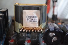
what about this core ? Marked N87
Attachments
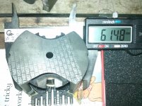
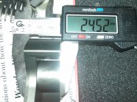
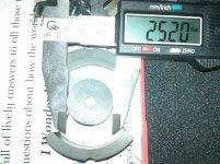
seems this: http://www.tauscher-transformatoren.de/assets/pdf/hf_63.pdf
Rated 1.2kVA @100kHz in push pull mode.
Rated 1.2kVA @100kHz in push pull mode.
99 % of the members here will never use the amplifier for a long time at more than 30 % of the rated power. So thermally it can be designed to much lower power. This means lower size transformator. But everybody have to make this decision on his own.
seems this: http://www.tauscher-transformatoren.de/assets/pdf/hf_63.pdf
Rated 1.2kVA @100kHz in push pull mode.
THANX pergo is it suitable for half bridge smps? example ir2110 with SG ic?
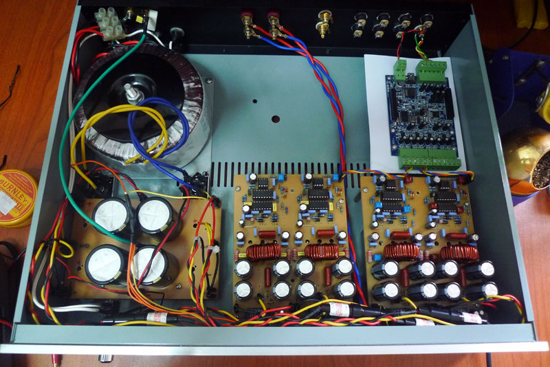
managed to make them stable enough that i've decided to case them up and use them as the resident sub amp.
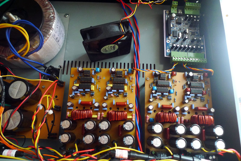
the output inductor goes too hot after 2 hours of movie run with huge bass so i've added an 80mm fan blowing to the pcb. gonna find another fan and do a permanent installation. the output mosfets are mounted to a heatsink underneath the pcb. the blue pcb on the top right is a 2x4 balanced minidsp to provide all the necessary dsp processing to the amp.
they're quad channel irs900d bridged into 2 channel powering a 4 ohm sub. switching frequency are reduced to 250khz, output inductor are made from T106-2 iron toroid with 21uh inductance. output mosfet are irfb5615.
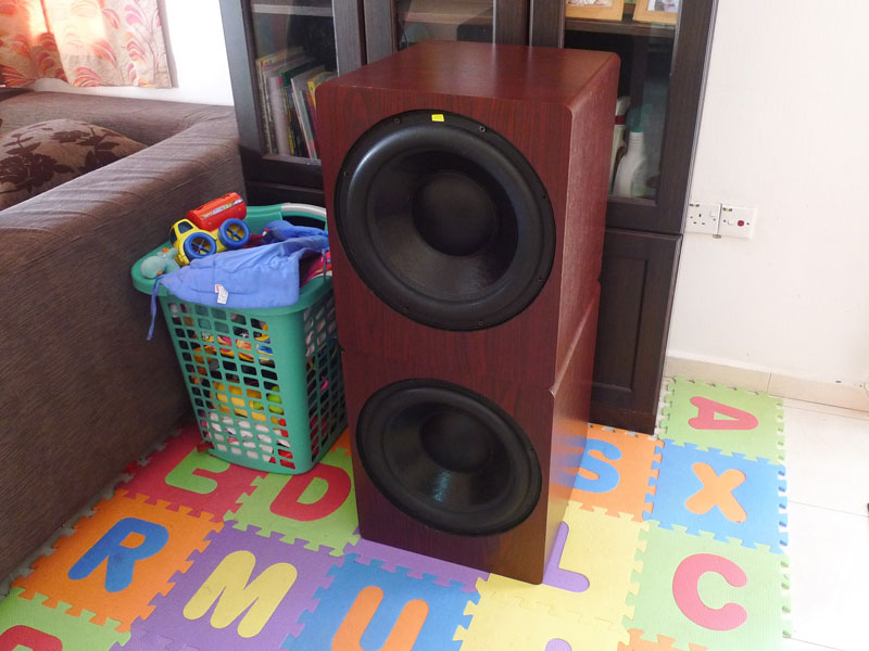
each of the bridged channel powers one of these 15" diy sub:
in room frequency response of the subs powered by the amp:
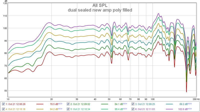
stopped at 102db before i could see any compression limit on the sub. don't wanna break the house.😱
cool work paskal what voltage are you using ? and the amp channels are in bridgemode? do the outputs heat
hi michelle
the pcb files or the schematic please
hi andrew pls post the pcb files of the irs3000d the one using bd 139 and 140 as buffers gate drivers
thanking you in advance stewin
hi michelle
the pcb files or the schematic please
Last edited:
cool work paskal what voltage are you using ? and the amp channels are in bridgemode? do the outputs heat
i measured 52V-0-52V after rectification and caps bank. the toroid is 35-0-35 500VA.Hi Paskal,
What rail voltages did you use?
for those of you guys that are considering about paralleling the output mosfet, i really don't think it's necessary. well unless you're gonna be driving them into 1 ohm. i'm only using irfb5615 rated at max 35A current and they have absolutely no problem into 2 ohm. they don't even heat up driving my subs at said volume.
and for what it's worth, more power are used to drive low frequency <80Hz compared to higher frequency. i really think a single pair of a relatively good mosfet stuck to a heatsink is enough. but that's just me.
to reduce the mosfet and ir2110 heat output to a minimum i've settle at 250khz switching frequency with 27 ohm gate resistor. i know some might argue that much gate resistance will increase thd but i found that higher gate resistor have no immediate effect to the sound quality of the sub.
higher gate resistor reduced the mosfet heat output to a bare minimum, reduced the idle current draw by about 20% (if i remember correctly) and reduced the ir2110 heat output considerably with no loss of sound quality that i can hear of. not scientific as i didn't exactly measure the SQ but changing back and forth between the 2 pcb i think i even prefer the pcb with 27 ohm gate resistor. maybe i'm bias but i still prefer minimum heat output compared to lower thd.
D
Deleted member 148505
the output inductor goes too hot after 2 hours of movie run with huge bass so i've added an 80mm fan blowing to the pcb.
Hi,
What's the size of your inductor? Is it T106 or T130?
Regards,
Last edited by a moderator:
- Home
- Amplifiers
- Class D
- UCD 25 watts to 1200 watts using 2 mosfets