Its the Vgs barrier of the output Mosfet and the Vbe additions of the mirror transistors. When running a high power Mosfet at 200-300mA its Vgs is sleeping enough and it can get you near 5V when compromising the mirror for voltage, that is why I recommended 7V floor, to have room. With low Vgs TTL Mosfets things change for margins.
Hi Salas, asking the same question Phisci asked. I'd like to use the REFLEKTOR for my pcm63 dacs. How would I get the voltage to 5V? Or is it just a matter of building the Japanese version? Or could one actually use a reg after like 7805?
Thanks
Thanks
As I wrote above it will work. Just use a 500R trimmer. The 5V Kazuo San build worked with the same IRF640 Mosfet as noted on his schematic along his preferred parts and values mods. Its not another version.
P.S. Using a chip reg after output is nullifying the effort, no real point. It could enhance as a pre reg but its small change.
Its the Vgs barrier of the output Mosfet and the Vbe additions of the mirror transistors. When running a high power Mosfet at 200-300mA its Vgs is sleeping enough and it can get you near 5V when compromising the mirror for voltage, that is why I recommended 7V floor, to have room. With low Vgs TTL Mosfets things change for margins.
Ok.. it needs a 7 V floor... I use 10v floor... but it can work outputting 5v, you just need to input 5 + 7 = 12v to have enough headroom right ?
I wonder why Kazuo-san chose the LE 820uF? Was it simply the value of the summed capacitance or that the 100KHz ESR is 5mOhms, thus 2.5mOhms in parallel?
Ok.. it needs a 7 V floor... I use 10v floor... but it can work outputting 5v, you just need to input 5 + 7 = 12v to have enough headroom right ?
No, 7Vout as a whole is enough for hot rod even *spared current pushes Vgs up.
P.S.
Vin-Vo is another story than VoMin, follow the normal practice with such regs. No less than 5V Vin-Vo not to goof up the CCS, 10V projecting for good measure against Tx & mains tolerance. Although you may find that this class of regs can regulate very near to Vin=Vo (one Vbe dif) the CCS will lose steam.
Vin-Vo is another story than VoMin, follow the normal practice with such regs. No less than 5V Vin-Vo not to goof up the CCS, 10V projecting for good measure against Tx & mains tolerance. Although you may find that this class of regs can regulate very near to Vin=Vo (one Vbe dif) the CCS will lose steam.
Looks like it. The Renesas low Vgs & high Yfs semi tells the lower threshold tale. Should had been easier to oscillate and to had needed the much different Zobel values due to high Crss.
Salas, for beginners like myself is there a place where I can read the thinking behind the shunt supplies and REFLEKTOR?
Looks like it. The Renesas low Vgs & high Yfs semi tells the lower threshold tale. Should had been easier to oscillate and to had needed the much different Zobel values due to high Crss.
Can you please suggest Zobel values?
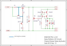
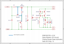
Kazuo-san used that Mosfet type to go 3.3V he certainly tested those values in his schema. If he will post he will explain further I suppose but he already mentioned that a quad of those regs are @ work in his latest Sabre DAC build.
Salas, for beginners like myself is there a place where I can read the thinking behind the shunt supplies and REFLEKTOR?
The grand-daddy of shunt regulator articles:
http://waltjung.org/PDFs/Dont_Shun_the_Shunt_Regulator.pdf
The Sabre DAC seems to be working well for me. But I have only poor oscilloscope. It is possible that I can not observe osc.P.S. Kazuo-san may post to discuss it & clear the assumptions?
When I move the position of the reg. board, it may sometimes oscillate obviously.
Honestly saying, I have no confidence the value of Zobel. I would like to wait for diyer's suggestions.
Attaching is the latest version.
Attachments
- Status
- Not open for further replies.
- Home
- Amplifiers
- Power Supplies
- The simplistic Salas low voltage shunt regulator