Hi
Thx for the answers
I have swap p1-p2 too 1kΩ and the volts over R10-11 is 1,0 volts now, then this okay ,
there is running 45 ma , but how about Q1-2 there is only running 4 ma,is that a problem ??
600 Ω drain resistor? , there is no 600 Ω resistor only 10 Ω with a 100 Ω pot
Nkdk
The 4 ma is why you had to increase the drain resistance. I think the Idss was specified to be 10 ma. Problem, I don't know? Have a listen and see what you think.
The 600 ohm was the combined total drain resistance, but that doesn't matter now that you have put in the new pot.
Measurements
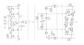
Hi there, i was hoping that someone could point me in the right direction regaring some measurements on the front end. I have a dip/overshoot on the negative curve that i would like to understand.
Voltage on the resistors are:
Left
R3/R4 = 64.66 - 64.69mV
R10 = 1.042 V
R11 = 1.037 V
Right
R3/R4 = 65.08 - 65.10mV
R10 = 1.038
R11 = 1.036
Here are som waveforms from the scope, the blue ones are for left channel and red for right. The input is 2Vp-p @ 5k, 50k and 100kHz.
Measured across R13.
......Like what connects to D+ or D- or S
Thanks🙂🙂
NS
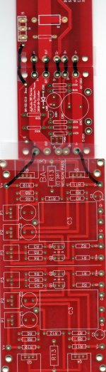
according to new BA3 frontend schematic, +D is signal out(to power amp)
I reckon -D would be signal ground
S ...? I only find that on old BA1 frontend, so I guess it goes nowhere now with new BA1/BA3 ?
Diyaudio store 🙂
Output of One side of the BA-3 frontend to D (GS) and ground G of One bias board, the same with the other output of the BA-3 Frontend and the other bias board.
D+ and D- are Only for the bias and S is the feedback sensing the bias current.
Output of One side of the BA-3 frontend to D (GS) and ground G of One bias board, the same with the other output of the BA-3 Frontend and the other bias board.
D+ and D- are Only for the bias and S is the feedback sensing the bias current.
Last edited:
so there must be a blog somewhere ?
D+ and D- are reminding me on BA3 balanced
sorry - I just didn't follow birth of pcbs
D+ and D- are reminding me on BA3 balanced
sorry - I just didn't follow birth of pcbs
Unfortunately Nelson's PDF and the bias and output board nomenclature are a bit different
I always had to think twice when connecting these parts and often.......did it the wrong way.
In this case D+and D- refer to the drains of the upper and lower outputstage and their bias. D (GS) !GS means gainstage, is the real input and the ground point nearby is for he shielded cable.
I always had to think twice when connecting these parts and often.......did it the wrong way.
In this case D+and D- refer to the drains of the upper and lower outputstage and their bias. D (GS) !GS means gainstage, is the real input and the ground point nearby is for he shielded cable.
Hi Zen,who made these pcbs ?
Cviller made them,the store sells them.
Did you build these for yourself?
I would like a different schematic, maybe I can follow it for these boards ,
Thanks!
NS
NS,
use this as an exercise to follow the schematic and figure out whats goibg on with the board. It isgood practice and will make you a better and more informed builder. I didnt even use the ba2 output but instead used the F4 boards. Took some work, but helped me understand the circuit and board better.
use this as an exercise to follow the schematic and figure out whats goibg on with the board. It isgood practice and will make you a better and more informed builder. I didnt even use the ba2 output but instead used the F4 boards. Took some work, but helped me understand the circuit and board better.
Hi Buzz,
Great Idea Buzz,I get it figured out!😀😀
Thanks ,
Buzz
NS,
use this as an exercise to follow the schematic and figure out whats goibg on with the board. It isgood practice and will make you a better and more informed builder. I didnt even use the ba2 output but instead used the F4 boards. Took some work, but helped me understand the circuit and board better.
Great Idea Buzz,I get it figured out!😀😀
Thanks ,
Buzz
Is your BA-3 a Complentary output stage or a SE output stage? The bias boards are different. The D or D+ would be the one the BA-3 output connects to. On the SE bias board (BA-1), D- is for the CCS gate signal. In the Comp bias board (BA-2) there should be no D-.
The store has some good schematics for the connection of the BA-1 & 2 bias boards to output boards but not BA-3? 😀
It just replaces the original common front end of BA-1 & 2.
The store has some good schematics for the connection of the BA-1 & 2 bias boards to output boards but not BA-3? 😀
It just replaces the original common front end of BA-1 & 2.
Hi 😀
Would some one help me out here I don't know where to connect the connection from the ba 3 to the bias board ,Like what connects to D+ or D- or S
Thanks🙂🙂
NS
I am very lazy to check this out, but I didn't think there was connection with the bias board and BA3 (front end).
I thought the bias board only connects to the output stage eg BA2 or BA1 output.
The connections can be made in more than one physical location that is electrically the same.
In the BA-1 the D+ (Both of them) of the bias bd is connected to the output of the BAGS (D) and the gates of all the top FETs on one of the 2 D labeled points. I think there is 5 wire connect points labeled D or D+.
In the BA-1 the D+ (Both of them) of the bias bd is connected to the output of the BAGS (D) and the gates of all the top FETs on one of the 2 D labeled points. I think there is 5 wire connect points labeled D or D+.
Thanks for all the reply's,
The ba-3 board is single out D is out G to gnd,
The bias board I think is made to operate with BA-1 It's balanced In and single out,so that's one single out for either board,am I correct so far,NOW here where I haven't got yet in building and smoke testing it,
The bias board,now ordinarily it was part of the front end then it changed to the output board single or complementary so 2 different circuits,
I after soon deep digging,D is D+ S is feedback from q102 on BASO V2.0 board,out to out D- to D-,I only have this output board so I can't say for the complementry board ,but It's bias is different,
The ba-1 is made for this output board,pad to pad,lol
I have ba-3 and ba-1 boards ,and I will build them soon It's the next build after Xoc1's TH,,,,,See any mistake or comments are welcomed!
Thanks for your help as always!
NS🙂
- Home
- Amplifiers
- Pass Labs
- Burning Amp BA-3