Yes, and you will find many detailed photos of this exceptional realization too.Is it on one of the pages of this thread ?
Look this post and before:
http://www.diyaudio.com/forums/solid-state/193923-simple-symetrical-amplifier-125.html#post3007067
Today I put my ear over the speaker and...
An externally hosted image should be here but it was not working when we last tested it.
There is HUM!
Faint, but present... normally not detectable... but head too close and "mmmmmrmrmrmmmrmmrmrmrrmrm".
I increased the fb current-feed resistors from 1k2 to 1k5, and the hum almost vanished. But, Iq is now 70mA; and only 3mA through the VAS.
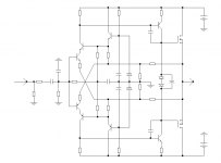
I suspected the PSRR. Off to my PC and simulated the following, a 15V capacitance multiplier. Seems okay in the sim. I was wondering whether others have experience with it, there. As it is known that the +-15V must be as clean as possible. Please. Or should I just double parallel-to-zener capacitance?
Thanks in advance.
P.S.- NO complaints about the music. It's as good as it was. With 1k2 current-feed resistor of course.
Faint, but present... normally not detectable... but head too close and "mmmmmrmrmrmmmrmmrmrmrrmrm".
I increased the fb current-feed resistors from 1k2 to 1k5, and the hum almost vanished. But, Iq is now 70mA; and only 3mA through the VAS.
I suspected the PSRR. Off to my PC and simulated the following, a 15V capacitance multiplier. Seems okay in the sim. I was wondering whether others have experience with it, there. As it is known that the +-15V must be as clean as possible. Please. Or should I just double parallel-to-zener capacitance?
Thanks in advance.
P.S.- NO complaints about the music. It's as good as it was. With 1k2 current-feed resistor of course.
Attachments
Are your grounding well designed (star) ? Did this hum stay the same when no source connected ?A capacitance multiplier is a good (very good) soundig choice for main power. For +-15 v, i would prefer a low noise regulated circuit.There is HUM!
Last edited:
My grounding is star. The hum is there with no source connected or input short to ground or zobel at the output. Otherwise the amp is very stable and sounds superb.
I think I will start with doubling the capacitors first.
I think I will start with doubling the capacitors first.
Return line from speakers direct to the common point of the PSU? Input grounds isolated from chassis and amps et direct to this point too ? Experiments for the best grounding point on the chassis ? No oscillation ?My grounding is star.
I use a cap multiplier on my TSSA. Without it there was a small hum but with the multiplier it is dead quiet.
There is HUM!
The power supply is common to the two channels? If so, in each case it is necessary to look for other connection point ground.
This can be time consuming.
To avoid this, apply a separate power supply. For each amplifier left and right channels of their own, independent.
Increasing the capacity of the filter capacitors will not help.
Last edited:
Return line from speakers direct to the common point of the PSU? Input grounds isolated from chassis and amps et direct to this point too ? Experiments for the best grounding point on the chassis ? No oscillation ?
Yes.
The power supply is common to the two channels? If so, in each case it is necessary to look for other connection point ground.
This can be time consuming.
To avoid this, apply a separate power supply. For each amplifier left and right channels of their own, independent.
Increasing the capacity of the filter capacitors will not help.
I built only a single board. I am talking about the capacitors parallel to the zeners. Thanks.
My build is double mono.
I plan to do the same.
I use a cap multiplier on my TSSA. Without it there was a small hum but with the multiplier it is dead quiet.
I was wondering if a cap-mult could help with the feedback current supply, in Class-AB SSA.
big local caps after the cap multiplier.
Ah, yes. Thank you. But as shown in the schema the cap mult is for the feedback and cascode current supply only, about 12mA. 1000uF?
Hi Shaan 
Few things to check for hum elimination
- one channel on, shorted input, check hum level, try different GND connections just to be shure that this is or not the problem
- after +/-15 V regulators (zener + BJT in your sch), connect 100 uF from each emmiter of regulating BJT (NPN/PNP) to GND, only elco parallel to zener at their bases is not enough
- if added 100 uF is lowering hum, you can further improve PSRR with use of TL431 for +/-15 V DC regulators
- further improvement is to use constant current generators from +/-15 V to mid feedback bridge points, this not only improves PSRR but immensely elevates the sound to the next level
So, Shaan, a lot of experimenting ahead
Hi Shaan
Few things to check for hum elimination
- one channel on, shorted input, check hum level, try different GND connections just to be shure that this is or not the problem
Hi Andrej.
Already checked. Grounding seems okay.
- after +/-15 V regulators (zener + BJT in your sch), connect 100 uF from each emmiter of regulating BJT (NPN/PNP) to GND, only elco parallel to zener at their bases is not enough.
Yes, will do so.
- if added 100 uF is lowering hum, you can further improve PSRR with use of TL431 for +/-15 V DC regulators
I would pay double for those precision devices, but couldn't source these here. Trying to make the best out of what's available.
- further improvement is to use constant current generators from +/-15 V to mid feedback bridge points, this not only improves PSRR but immensely elevates the sound to the next level
Yes I have that checked. This will be my next job. I have read through your CCS implementation posts. Very impressive indeed.
So, Shaan, a lot of experimenting ahead
Yup, I'm on it.
Last edited:
As i said in previous posts, separated power supplies to power a stereo amp is far to be a the best solution for several reasons.I plan to do the same.
1: A double sized PSU will benefit at each channel separately during transients.
2- The localization will be far better with a single PSU, as any change in the PSU voltages will be applied to the 2 channels simultaneously, so the image of the instrument will not move to the center during hight transients.
The only cons would be the separation (cross talk), no difference in real wold, and who care ?
On my amp, i used a big toroidal trasfo (1100 VA), and big caps. Adding this cap multiplier had changed the sound in an incredible way to the top:
http://www.esperado.fr/images/stories/SSA-Crescendo/supply.gif
PS: I allway spend a lot of time to find the best position on the chassis to connect the earth/ground. Sometimes, it is surprising.
I use the following cabling method with symmetrical cable for all the modulation connectors (out is the left):
It prevent any current in the shield to leak in the the modulation wire, and prevent the hf to enter in the feedback loop of the source (IM distortion).
You will have to check all combination in the sens where all the power supply wires of the different equipments are connected the the AC outlets, to minimise the leakage, sensing the voltage between the chassis grounds (unconnected together).
The only ground cable to be connected to the ground outlet will be the Power amp one.
Attachments
Last edited:
Begin with the power amp alone. Isolate the ground wire from the outllet and measure the voltage between the ground wire and the outlet's ground: invert the power cables, choose the sens where the voltage is minimum, reconnect the ground.
Remove from your preamp any ground in the power plug. Without connecting preamp to the amp, invert the power wires of your preamp, measure the voltage between the ground of the modulation cable and the Power amp input ground. Chose the sens where leakage voltage is minimum.
Keep your measurement instrument as-it and connect the most used source (CD ?) both power and modulation cable , do the same power cable inversion of this source to find the best position of the plug, keep your plugs connected and go to the next source...etc..
Mark all your plugs to recover your settings if you unplug any element, plug the modulation cable between your preamp and your amp.
Optimized.
Last edited:
On my amp, i used a big toroidal trasfo (1100 VA), and big caps. Adding this cap multiplier had changed the sound in an incredible way to the top:
http://www.esperado.fr/images/stories/SSA-Crescendo/supply.gif
Hello
There is a perfume of Jacovopoulos Hexo3 🙂, good job !
Best regards
Roger
Yes, just a stabilized source of voltage with no feedback (requested for good sound). I just found the schematic of this hexo3 on Google (nice very simple amp, can be adapted to SSA too), his regulated supply looks exactly the same. Not a surprise, there is no hundred ways to do this, but, wow, you have an amazing memory.There is a perfume of Jacovopoulos Hexo3r
Hello
I made this psu with mj11015/11016 and second TL431 instead of zeners, I have not yet found a solution to replace the r380 by a current source (63V at startup).
I love this thread and I awaiting the Csa
Good job
Regards
Roger
I made this psu with mj11015/11016 and second TL431 instead of zeners, I have not yet found a solution to replace the r380 by a current source (63V at startup).
I love this thread and I awaiting the Csa
Good job
Regards
Roger
- Status
- Not open for further replies.
- Home
- Amplifiers
- Solid State
- Simple Symetrical Amplifier