Υou also forgot to make the anode resistors 100K. With feedback, you are going to need the gain.
Actually I would like to maintain the 47k anode resistor and increase gain only when feedback is switched on.
I should find a simply way to do it 😕
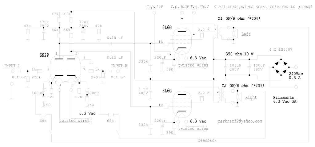
Corrected schematic:
note: I increased anode resistor of 6N2P from 47k to 56k (small gain adjustment) but if feedback is used I'd suggest to increase it up to 100k.
note: I increased anode resistor of 6N2P from 47k to 56k (small gain adjustment) but if feedback is used I'd suggest to increase it up to 100k.
Last edited:
With UL in this setup, what would the effect be of changing the value of the screen resistors? Is dropping the screens below the plates the major consideration? Is it merely a tradeoff between power and safety? I ask because I think I've generally seen lower screen resistor values on UL and I'm ignorant on UL's considerations.
With UL in this setup, what would the effect be of changing the value of the screen resistors? Is dropping the screens below the plates the major consideration? Is it merely a tradeoff between power and safety? I ask because I think I've generally seen lower screen resistor values on UL and I'm ignorant on UL's considerations.
6L6 screen grid should not exceed 250V, this circuit has 290V plate voltage, the screen resistor is calculated for 50V voltage drop.
Last edited:
68k/150R will give you another feedback fraction than 68k/1k.
What is your target?
Right, I think I shuld lower feedback resistors as low as 10K, do you agree?
Last edited:
If the open loop gain is something like 50x (I havnt calculated the Aol) then a 10k feedback resistor should give about 5dB feedback. Under the same conditions a 68k resistor would give you less than 1dB feedback.Right, I think I shuld lower feedback resistors as low as 10K, do you agree?
jjman said:With UL in this setup, what would the effect be of changing the value of the screen resistors? Is dropping the screens below the plates the major consideration? Is it merely a tradeoff between power and safety? I ask because I think I've generally seen lower screen resistor values on UL and I'm ignorant on UL's considerations.
6L6 screen grid should not exceed 250V, this circuit has 290V plate voltage, the screen resistor is calculated for 50V voltage drop.
270V is the max screen grid voltage for old 6L6 types, like the original metal can ones, or 6L6G, 6L6GA (from RCA Tube Manual).
The Tung-Sol 6L6WGB was rated for 300V on the screen grid (grid #2).
6L6GC can take 500V (!) on the screens "in push pull circuits where the screen of each tube is connected to a tap on the plate winding on the output transformer." (From GE Tube Manual)
So, with screen voltages above 300V, use a 6L6GC.
The screen grid resistor in a UL connection is a "screen stopper," is it not? It's not a decoupling resistor with a filter capacitor. The screen stopper goes from the screen grid to the 40% tap on the OPT. 2k2 is a large value in this spot, but I don't think it does any harm for it to be a large value. You could try the more usual 470R and see if it makes any difference at all.
--
Last edited:
The screen resistor value does have an effect on distortion.
The larger the value, the lower the distortion?
Any other limiting factors? I haven't seen this discussed, so am curious...
--
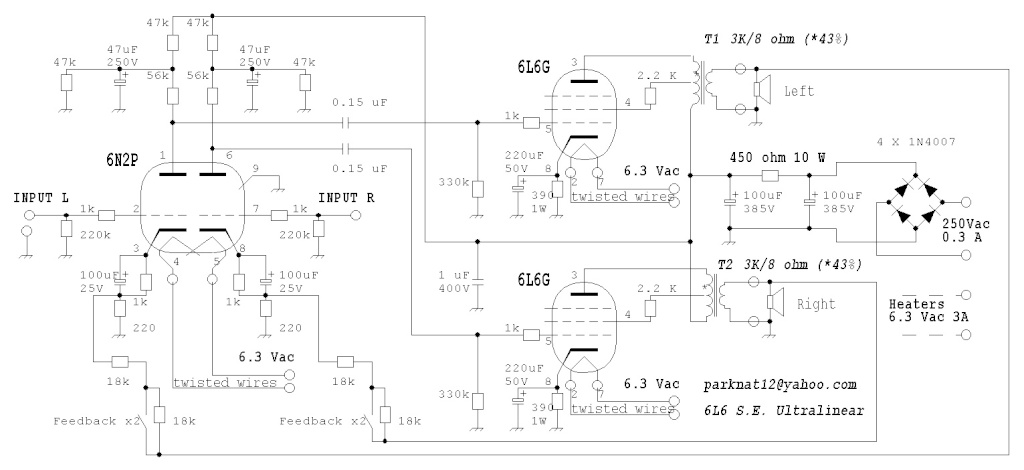
at the end, after two weeks of tests, I finished my 6L6 S.E. Ultralinear 🙂
The sound is very impressive!
Thank you all for your precious help.
The sound is very impressive!
Thank you all for your precious help.
Last edited:
- Status
- Not open for further replies.
- Home
- Amplifiers
- Tubes / Valves
- Stereo class A 6+6W - 2x 6L6G 1 x 6N2P