Hi,
I would like to investigate about the actual/perceived/imagined superiority of current feedback, and possibly to pinpoint what exactly makes it superior (if indeed it actually is).
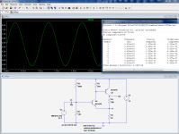
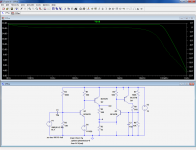
As a study subject, I propose to use a very simple, quasi-canonical form of a CFB amplifier, the CFP with gain.
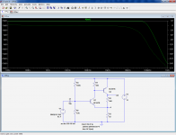
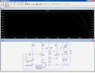
The two first pics show the linearity and frequency performances of the circuit.
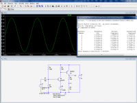
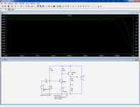
The interesting thing with the sim is that it allows the transformation of this ideal CFB amp into an identical ideal VFB stage.
That can be done with an arbitrary voltage source (the next two pics).
As could be expected, the linearity has improved thanks to to the increased loop gain, but somewhat more surprisingly the bandwidth also increases.
I would like to investigate about the actual/perceived/imagined superiority of current feedback, and possibly to pinpoint what exactly makes it superior (if indeed it actually is).
As a study subject, I propose to use a very simple, quasi-canonical form of a CFB amplifier, the CFP with gain.
The two first pics show the linearity and frequency performances of the circuit.
The interesting thing with the sim is that it allows the transformation of this ideal CFB amp into an identical ideal VFB stage.
That can be done with an arbitrary voltage source (the next two pics).
As could be expected, the linearity has improved thanks to to the increased loop gain, but somewhat more surprisingly the bandwidth also increases.
Attachments
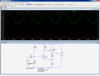
Now that we have noticed the differences, we can begin to try to even them out, to try and see where the two versions diverge.
Let's see the effect of the loading on the feedback point, by adding an equivalent circuit, while retaining the VFB configuration: it begins to look more like the CFB incarnation, but do not be fooled by the graph: LTspice has automatically scaled it, and the 1GHz intercept is at -4dB instead of -25dB.
Let's see the effect of the loading on the feedback point, by adding an equivalent circuit, while retaining the VFB configuration: it begins to look more like the CFB incarnation, but do not be fooled by the graph: LTspice has automatically scaled it, and the 1GHz intercept is at -4dB instead of -25dB.
Attachments
I don't think so. This rather crude first tentative does have issues, but normally R2 is not part of them. I could be mistaken of course. This is an exploration trip, and I do not know where it will lead usIsn't R2 in the wrong place?
OK, I should have explained more clearly what I did exactly.Isn't R2 in the wrong place?
I thought the diagrams were sufficient, but that is not necessarily the case for people unfamiliar with spice.
I started with a classical CFB circuit; I then buffered the feedback point using a spice ideal buffer: a voltage source that simply copies its input, without loading or delay.
I then attempted to reproduce the behavior of the initial CFB circuit by loading again the feedback point with a (not so!) similar load.
That's where we currently are
The first attempt to revert to the CFB characteristic by loading the feedback divider has failed.
The reason is simple: in the real CFB, the impedance is in fact different, because Q1's base is not at a fixed potential: it follows the signal, and thus bootstraps the emitter's impedance.
This in itself is quite interesting: it means the so called CFB is not really a pure CFB: it also displays attributes of VFB.
In order to have a really pure CFB, we would need to sufficiently reduce R1 to make R3 unnecessary.
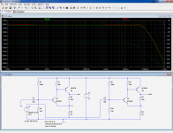
So, back to our CFB-like VFB, all we need to do is to equalize the base potentials of Q1 and Q3.
And this time, it works:
The reason is simple: in the real CFB, the impedance is in fact different, because Q1's base is not at a fixed potential: it follows the signal, and thus bootstraps the emitter's impedance.
This in itself is quite interesting: it means the so called CFB is not really a pure CFB: it also displays attributes of VFB.
In order to have a really pure CFB, we would need to sufficiently reduce R1 to make R3 unnecessary.
So, back to our CFB-like VFB, all we need to do is to equalize the base potentials of Q1 and Q3.
And this time, it works:
Attachments
We can now try to confirm what we discovered: the canonical CFB is in fact a closet VFB circuit.
We just have to compare the magnitude of the currents in the sensor transistor, Q1 and the output divider: (the current into Q1 is 72µApp)
Yet, this very light loading is sufficient to cause significant errors, as we have seen earlier.
We just have to compare the magnitude of the currents in the sensor transistor, Q1 and the output divider: (the current into Q1 is 72µApp)
Yet, this very light loading is sufficient to cause significant errors, as we have seen earlier.
Elvee, I am sorry to see that you are a little lonley, to some it is clear but maybe some of audience don't quite understand what you are proving or disproving.
I also think that newer folk is afraid to even ask what is being discussed not understanding the difference or what CFB actually tries to accomplish.
I also think that newer folk is afraid to even ask what is being discussed not understanding the difference or what CFB actually tries to accomplish.
Last edited:
maybe some of audience don't quite understand what you are proving or disproving..
Yes. Right now I see it like Elvee is comparing apple to an orange. Not sure whether he is trying to prove which one is more spherical than the other, or more yellowish... But I'm waiting... for the conclusion 😀
Member
Joined 2009
Paid Member
for me they (CFB and VFB) as described are both voltage feedback, but this is one of those annoying semantics issues. what I mean is that the feedback is sensing the voltage at the output and feeding a fixed portion of it back to the inverting input. what people call a current feedback loop is one in which the input impedance of the inverting input is relatively low and what people call a voltage feedback loop is one in which the input impedance of the inverting input is high.
I don't understand all the differences between them, but I've consistently read that the CFB type feedback has higher bandwidth / higher stability / less compensation. Or put it another way, it has less phase shift. For a feedback loop, this is highly desirable. I have only explored these differences by using either an LTP or a JLH style singleton and they have other factors that differ between how they operate to obscure an understanding of the differences between CFB and VFB in my mind. so what you are doing Elvee looks interesting.
for me, true current feedback is where the output current is sensed and converted to a voltage which is then applied to the inverting input. again semantics. an example is the Aleph current source, in which the output current is sensed by a resistor, the same resistor conveniently converting it to a voltage signal for feedback.
sorry for the ramble !
Last edited:
The essential difference is that the current feedback amplifier can be seen as a transimpedance amplifier in which the output voltage is controlled by a fed back current.
The transimpedance can be put as
Zt = Go/(1 + joGoCc)
Go= the open loop d.c. gain and Ct is the Miller compensation capacitor.
This type of amplifier has the advantage of a constant bandwidth despite closed loop gain because it does not have a constant gain bandwidth like a voltage feedback op amp.
rcw
Last edited:
But I'm waiting... for the conclusion 😀
I have no conclusions ready. I am freely reflecting on the subject, and I am sharing my thoughts.
I think there are a number of misconceptions about all this: firstly, in actual circuits the difference between the two is not as clear cut as many would like to believe, and secondly the virtues or flaws attributed to one or the other seem to disappear as soon as you normalize the conditions of the comparisons.
Bigun's opinion looks convergent with mine.
What could emerge of all this is a better understanding of both topologies (if they are actually distinct), and better circuits, making optimum use of the phenomenons involved, to create ideal and pure VFB or CFB circuits.
As Bigun commented semantics have a lot to do with it.
For instance the standard type of op amp can be looked at as a current feedback amp when connected in the inverting mode, because the feedback is converted to a current by the feedback resistor and summed at the virtual earth point.
There is also the direct coupled three transistor amplifier, (much used in audio at one time), that uses d.c. feedback to the emitter of the input transistor. Since this arrangement varies the open loop gain with the feedback ratio it also satisfies another property of current feedback op amps.
In the expression I posted note that it has a compensation capacitor in it and the assumption is made that the amplifier has a fixed integrated capacitor for this, the current feedback topology allows a constant bandwidth over a range of gains unlike in a similar arrangement in a voltage feedback amp, these having a constant gain bandwidth product and not a constant bandwidth.
In the end I can see no particular advantage for audio anyway and they are most useful at frequencies well above the audio band.
rcw
Could you elaborate on that, I don't quite visualize it?There is also the direct coupled three transistor amplifier, (much used in audio at one time), that uses d.c. feedback to the emitter of the input transistor. Since this arrangement varies the open loop gain with the feedback ratio
This is the three transistor configuration as it appears in a Burr Brown application note.
The second configuration is the addition of an emitter follower that isolates the feedback loop and gives constant open loop gain unaffected by the feedback components this is then the classical voltage feedback op amp topology.
The third diagram is the basic current feedback topology. You can see that it is a symmetrical version of the three transistor amp, with a complimentary emitter follower on its output and emitter followers buffering its input.
rcw
.
Attachments
OK, this circuit is identical to my first one, except for the emitter follower output.This is the three transistor configuration as it appears in a Burr Brown application note..
This addition means that you can lower almost arbitrarily the gain setting resistors, and get a matching increase in OL gain (and departing from the CFB "philosophy")
That one is the "real life" version of my second circuit, with the spice buffer replaced with an emitter followerThe second configuration is the addition of an emitter follower that isolates the feedback loop and gives constant open loop gain unaffected by the feedback components this is then the classical voltage feedback op amp topology.
Yeah, for high enough transimpedance gains, this structure will have a behavior indistinguishable from a regular VFB in all practical circuits (except comparators).The third diagram is the basic current feedback topology. You can see that it is a symmetrical version of the three transistor amp, with a complimentary emitter follower on its output and emitter followers buffering its input.
Last edited:
...
Yeah, for high enough transimpedance gains, this structure will have a behavior indistinguishable from a regular VFB in all practical circuits (except comparators).
Elvee,
Not sure I'm following your train of thought here, are you saying that as long as the VFB topology does not "run out of available input stage current change" it behaves similarly to CFB?
Thanks
-Antonio
The amplifier bandwidth is limited by the current available to slew the compensation capacitor.
In an amplifier with no access to the compensation capacitor that is stabilised for unity gain the bandwidth is limited by the value of this capacitor, and in the voltage feedback scheme the current available to slew this capacitor is fixed.
In the CFB topology however the feedback resistor sets the current available to slew this capacitor, thus over a given range the bandwidth is only dependent upon this resistor, this is the Go term in the expression that I posted, Zt is constant for a given Cc provided that Rf is also constant, this is true over the range specified in the data sheets.
Your modeled circuits do not have the pole splitting capacitor, so I am assuming that the slew is limited by the transistor characteristics alone, putting the capacitor in the simulation might be informative.
rcw
- Status
- Not open for further replies.
- Home
- Amplifiers
- Solid State
- Is the CFB topology superior, and why?