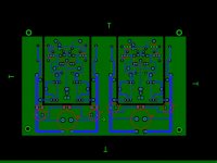
Here is what I've concocted. Funny, but after putting the rat's nest together, it all started to take shape just like Mr. Marsh's board.
I did mine all manually. Interesting similar results -- there must be 'rules' the auto feature goes by which are similar to what I learned.
I did mine all manually. Interesting similar results -- there must be 'rules' the auto feature goes by which are similar to what I learned.
It was all done manually. 😉 What I did was follow YOUR rules that you posted many pages back. I looked at your board and noticed how you followed the schematic. I then laid out the parts in random fashion and connected all the parts. It was pretty much a rat's nest! So I started moving all the parts around. When I pretty much had it completed, I looked at your board again and it was nearly a dup! It boils down to your explanations making good sense to me. 🙂
Thx for the feedback....
BTW - I always do a layout that looks like I am drawing the circuit on pcb. It is also easier to trouble-shoot against the schematic.
BTW - I always do a layout that looks like I am drawing the circuit on pcb. It is also easier to trouble-shoot against the schematic.
Here is what I've concocted. Funny, but after putting the rat's nest together, it all started to take shape just like Mr. Marsh's board.
There's a feature in Ultiboard "Auto Parts Placement" -- for audio it's virtually unuseable since, as Richard points out, you have to keep the high current traces away from the small signal traces. You can use some aspects of this feature if you lock the high current and input components into place and it helps "intuit" where parts should go.
And of course, netlisting the schematic to the layout gives you automagically a ratsnest that's 100% identical to your schematic - no errors to chase.
Of course, if you make an error in the schematic, that is then faithfully transferred to the PCB as well..😉
jan
Of course, if you make an error in the schematic, that is then faithfully transferred to the PCB as well..😉
jan
all good advice...it would save me the QA time to make sure my boards are good and I don't smoke something $$$
Another thing i do during development/prototyping is put the ground plane or the shield plane on the bottom and the signal traces on the top. That, along with a schematic like layout, makes modifications and testing, probing and measuring easier.
These pcb ways make prototyping a new design easier and maybe trouble-shooting during development. Also, later if a part fails.... and for modifying the circuit... easy to cut trace and/or add something without tearing the pcb out and getting to the traces on the bottom.
-RNM
These pcb ways make prototyping a new design easier and maybe trouble-shooting during development. Also, later if a part fails.... and for modifying the circuit... easy to cut trace and/or add something without tearing the pcb out and getting to the traces on the bottom.
-RNM
Last edited:
I am doing my best not to reinvent wheels. 😉
BTW, I bought more 2n5460 jfets. The ones I sourced from HK are mostly junk. I bought a small set from a guy in Florida that actually turned out pretty darn good and they don't tend to drift. The bad news is that he only had a few more left and I bought those up this morning.
I just bought 20 OnSemi 2n5457 that were recovered from some equipment. I'll have news if they are any good once I receive them.
yep, but I'm a dumb bunny sometimes. I noticed the power ratings are lower on these devices so i wasn't sure I could just pop these right into place (so to speak).
I found an eBAY low distortion sine wave signal source on pcb, loaded/built for $39. The fixed 1 KHz signal only has .00005% thd. That works for me. Ordered 2 of them. Look under electronics test equipment.
I measured the units -- 2ea of the 1Khz and found that only the even harmonics are very low. the odd harmonics are not so great -- -88-90db for 3rd and 5th and further down the road is still high. Not better than the AP. rats!
I'll contact the source of these and see what he says.
-RNM
Jan,
I got the transistors today. Thanks! They arrived in great condition. 😀
Actually you are one short. After unpacking box # 47 (or maybe it was # 55) from the move yesterday, one lonely 210 fell out. I'll get it to you for sure 😉
I'd be curious how they match up, hope they are usefull for you.
jan
Jan,
I pulled out the Heathkit IT-18 last night and beta on the NPNs runs about 140 to 160, while PNPs run from about 160 to 180. I'll get plenty of useful ones from the set.
Maybe SY can toss that 1 lonely transistor in the mail when you come to the States for Janneman 2012 Chicagofest! 😉
I pulled out the Heathkit IT-18 last night and beta on the NPNs runs about 140 to 160, while PNPs run from about 160 to 180. I'll get plenty of useful ones from the set.
Maybe SY can toss that 1 lonely transistor in the mail when you come to the States for Janneman 2012 Chicagofest! 😉
Mr. Marsh,
I'll be checking for Vbe this weekend. Details to follow.
@jackinnj:
Coming up with a revision to my board will be cinch for those SMT fets..plenty plenty in stock at Mouser. I'll build a TO-92 version and an SMT version. Plenty of boards in my parts bin and plenty of etch solution. 🙂
I'll be checking for Vbe this weekend. Details to follow.
@jackinnj:
Coming up with a revision to my board will be cinch for those SMT fets..plenty plenty in stock at Mouser. I'll build a TO-92 version and an SMT version. Plenty of boards in my parts bin and plenty of etch solution. 🙂
Mr. Marsh,
I'll be checking for Vbe this weekend. Details to follow.
@jackinnj:
Coming up with a revision to my board will be cinch for those SMT fets..plenty plenty in stock at Mouser. I'll build a TO-92 version and an SMT version. Plenty of boards in my parts bin and plenty of etch solution. 🙂
For the F5 boards i had burned in China i allowed for use of SMT JFETs -- i should've thought of that when I did the headphone boards, but hadn't realized that there was a shortage of TO-92 parts...and as i mentioned previously, you could use GR rated 2sk170's or bf862.
On my part, it's a hard-headed approach to staying as faithful to the article.
But I'll shed no tears if I have to use the SMT parts. 😉
But I'll shed no tears if I have to use the SMT parts. 😉
I measured the units -- 2ea of the 1Khz and found that only the even harmonics are very low. the odd harmonics are not so great -- -88-90db for 3rd and 5th and further down the road is still high. Not better than the AP. rats!
I'll contact the source of these and see what he says.
-RNM
source says there is nothing wrong with them... must be my AP needs calibration... ??
yes, as a rookie, I was tempted to buy used stuff on ebay dirt cheap. Then I started to realize how will I know if it's defective? I later read somewhere to pay for a re-calibrated unit.
Update - the MOT fets I bought are junk. As soon as I put them on my breadboard to test Idss, they became extremely hot. Boy oh boy...
So I also worked on the SMT layout and I'll order some of those Fairchild SOT23 fets. But I bet I have close enough matching on those FETS I found in FLA and in Thailand. So on the fets, I'm good to go.
SMT version
On the left channel, I laid it out for the smt versions of the jfets. I noticed on the Fairchild Semi datasheet that drain and source are inter-changeable. So it must be symmetric it seems.
Also note that I added film caps from rail to ground and also a film cap that goes from rail to rail. Mr. Marsh mentions this in the article. I lucked out and got the last of the Wima PPS box caps in stock. These are the Wima MKI series. Nice and small with 5mm lead spacing.
Attachments
- Home
- Amplifiers
- Headphone Systems
- Marsh headphone amp from Linear Audio