The amplifiers I have posted have started an audio revolution. Many audio houses will revise their designs within the next few years, I am glad that audio is headed in the right direction. A time will come when all amplifiers will sound the same and it will be hard to choose a camp.
I was in an art museum yesterday and saw the gold coins used by the roman empire, the level of development and art work is of very high standard.
The art work all the way back from 400BC, shows that man has always been smart. We discover and loose technologies depending on what is going on on the planet.
The uniformity of nature tells us that if there is a sign of life in one solar system(that is earth), then there must be life on another solar system, whether that solar system is our own or another.
The audio/electronics industry will be doing all they can to shut down us diyers.
Unfortunately it has already started... You see much more smd version of everything, pushing opamp more and more... But we will survive this and build better stuff!
Do
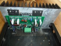
After a week of building, I have now had the opportunity to connect SYMASEF with my Copland 288 – Aikido pre and Sony / Fostex speakers. It has so far not been opportunity to any thorough assessment of how SYMASEF plays, compared to my two Golmund Clons (also "the worlds best amplifier") + NAD 208. A comparison is somewhat difficult, since my two Goldmund / NAD 208 plays in a completely different setup than what SYMASEF does now. In this setup, I take the signal from a NAS (Synolgy) to the Lampizator Transport with Squeezebox Duet to a heavily modified Behringer DCX 2496. Speakers are Magnepan 1.6. This setup plays in a different "league" than in what SYMASEF now are placed in the for testing. But even now I can confirm that SYMASEF have nothing to be "ashamed" of. They play well throughout the area I am able to hear (30Hz-14000 Hz). Possibly there will be an opportunity for a deeply listening test later, and after the week of summer holidays in Denmark is done.
When it comes to the actual construction, I would like to point out:
PCB is not well enough adapted to the opportunities to use components that need larger holes to be soldered on the PCBs under side. Some components I have therefore, soldered just on the top of the PCB, which have giving me unnecessary trouble and associated troubleshooting due to poor contact. This should be corrected to the next distribution of the “free” PCB.
Although all components are printed on the silkscreen, I miss a drawing of PCBs component side. The photo on website is too difficult to "read" for precise control.
When the PCB is placed on the heat sink, it is difficult to get access for the bias setting (not R9 as referred to in several posts, but over one of R13,
R 14). Why not add two measuring points in parallel with R 13, R14. It will facilitate the adjustment of the bias.
I have generally followed the component instructions printed on the silk screen. MJE 15034/35 has been difficult to access. I have instead used 2SC2238A/2SA968A.
For R7, R9, R30 and R34, I have used 2 Ohm instead of the recommended 1 Ohm. That's what I had left, and I expect that this will not have any significant influence on the amplifier's performance. 33pF also used instead of 39 pF. Also irrelevant.
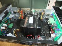
What probably distinguishes my SYMASEF from others, I guess, would be that the power supplied come from a stabilized circuit (see separate photo of print). This PCB, I have had left since the middle of the eighties, when I built an amplifier designed by Michal Madsen / Rene Jørgensen of the Danish High Fidelety (“retired”). The magazine brought a number of very good DIY articles. Technical data taken from the magazine:
Input voltage: 42 - 48 V DC.
Output voltage: 35 - 40 V DC.
Output impedance: 20 Hz-20 kHz: <1 milliohm
Output Current: + / - 6 amps
Output 10 msec + / - 30 amps
With a stabilized power supply, I had assumed that SYMASEF would be totally free from hum. Unfortunately, it is not. Admittedly, it is after a few hours of operation much less audible, but still you may hear a faint hum from the speakers, which annoys me.
Maybe some comments on how I have grounded the amplifier:
Each power supply has a "ground plane" (a screw). Here meets all the wires from;
Ground on SYMASEF PCB
Speaker ground
The connection from the 0-point between the to big el-lyts
0-leader from the transformer is only connected to the 0-point between the big el-lyts.
Closest to the input socket, screen is connected to the chassis.
The same connections is done in both channels.
My friend Roar (Malmin) says that R18 of 2.7 Kohm could benefit from a much lower value. Any comment???
Eivind Stillingen
When it comes to the actual construction, I would like to point out:
PCB is not well enough adapted to the opportunities to use components that need larger holes to be soldered on the PCBs under side. Some components I have therefore, soldered just on the top of the PCB, which have giving me unnecessary trouble and associated troubleshooting due to poor contact. This should be corrected to the next distribution of the “free” PCB.
Although all components are printed on the silkscreen, I miss a drawing of PCBs component side. The photo on website is too difficult to "read" for precise control.
When the PCB is placed on the heat sink, it is difficult to get access for the bias setting (not R9 as referred to in several posts, but over one of R13,
R 14). Why not add two measuring points in parallel with R 13, R14. It will facilitate the adjustment of the bias.
I have generally followed the component instructions printed on the silk screen. MJE 15034/35 has been difficult to access. I have instead used 2SC2238A/2SA968A.
For R7, R9, R30 and R34, I have used 2 Ohm instead of the recommended 1 Ohm. That's what I had left, and I expect that this will not have any significant influence on the amplifier's performance. 33pF also used instead of 39 pF. Also irrelevant.
What probably distinguishes my SYMASEF from others, I guess, would be that the power supplied come from a stabilized circuit (see separate photo of print). This PCB, I have had left since the middle of the eighties, when I built an amplifier designed by Michal Madsen / Rene Jørgensen of the Danish High Fidelety (“retired”). The magazine brought a number of very good DIY articles. Technical data taken from the magazine:
Input voltage: 42 - 48 V DC.
Output voltage: 35 - 40 V DC.
Output impedance: 20 Hz-20 kHz: <1 milliohm
Output Current: + / - 6 amps
Output 10 msec + / - 30 amps
With a stabilized power supply, I had assumed that SYMASEF would be totally free from hum. Unfortunately, it is not. Admittedly, it is after a few hours of operation much less audible, but still you may hear a faint hum from the speakers, which annoys me.
Maybe some comments on how I have grounded the amplifier:
Each power supply has a "ground plane" (a screw). Here meets all the wires from;
Ground on SYMASEF PCB
Speaker ground
The connection from the 0-point between the to big el-lyts
0-leader from the transformer is only connected to the 0-point between the big el-lyts.
Closest to the input socket, screen is connected to the chassis.
The same connections is done in both channels.
My friend Roar (Malmin) says that R18 of 2.7 Kohm could benefit from a much lower value. Any comment???
Eivind Stillingen
Attachments

Make r18=1.8k watch your swing into the drivers. Your hum problem could be you might have to lift the input gnd by a 10 ohm resistor. Evette
I did not have any hum issues what so ever! And i had no problem getting to the bias pot either!
Scope the amp and see if its oscillating, this can draw alot of current and cause hum.
Scope the amp and see if its oscillating, this can draw alot of current and cause hum.
First off. Congratulations Liliya  . I have been very thirsty waiting for any result and just as I was snoozing bang, you load me up, thank you. Now I prepare comments.
. I have been very thirsty waiting for any result and just as I was snoozing bang, you load me up, thank you. Now I prepare comments.Time will tell, however no one has provided feedback on how SYMEF sounds on the likes of Magnepan 1.6 and family. This will be a first.my two Golmund Clons (also "the worlds best amplifier") + NAD 208. A comparison is somewhat difficult, since my two Goldmund / NAD 208 plays in a completely different setup than what SYMEF does now. In this setup, I take the signal from a NAS (Synolgy) to the Lampizator Transport with Squeezebox Duet to a heavily modified Behringer DCX 2496. Speakers are Magnepan 1.6. This setup plays in a different "league" than in what SYMEF now are placed in the for testing. But even now I can confirm that SYMEF have nothing to be "ashamed" of. They play well throughout the area I am able to hear (30Hz-14000 Hz). Possibly there will be an opportunity for a deeply listening test later, and after the week of summer holidays in Denmark is done.
PCB is not well enough adapted to the opportunities to use components that need larger holes to be soldered on the PCBs under side. Some components I have therefore, soldered just on the top of the PCB, which have giving me unnecessary trouble and associated troubleshooting due to poor contact. This should be corrected to the next distribution of the “free” PCB.
Although all components are printed on the silkscreen, I miss a drawing of PCBs component side. The photo on website is too difficult to "read" for precise control.
When the PCB is placed on the heat sink, it is difficult to get access for the bias setting (not R9 as referred to in several posts, but over one of R13,
R 14). Why not add two measuring points in parallel with R 13, R14. It will facilitate the adjustment of the bias.
My team will try to make future PCBs more adaptable. I do however appreciate your creativity in making it work for you. You do have one very exotic amplifier.
The SYMEF has survived many adaptations.I have generally followed the component instructions printed on the silk screen. MJE 15034/35 has been difficult to access. I have instead used 2SC2238A/2SA968A.
For R7, R9, R30 and R34, I have used 2 Ohm instead of the recommended 1 Ohm. That's what I had left, and I expect that this will not have any significant influence on the amplifier's performance. 33pF also used instead of 39 pF. Also irrelevant.
What probably distinguishes my SYMEF from others, I guess, would be that the power supplied come from a stabilized circuit (see separate photo of print). This PCB, I have had left since the middle of the eighties, when I built an amplifier designed by Michal Madsen / Rene Jørgensen of the Danish High Fidelety (“retired”). The magazine brought a number of very good DIY articles. Technical data taken from the magazine:
Input voltage: 42 - 48 V DC.
Output voltage: 35 - 40 V DC.
Output impedance: 20 Hz-20 kHz: <1 milliohm
Output Current: + / - 6 amps
Output 10 msec + / - 30 amps
With a stabilized power supply, I had assumed that SYMEF would be totally free from hum. Unfortunately, it is not. Admittedly, it is after a few hours of operation much less audible, but still you may hear a faint hum from the speakers, which annoys me.
Maybe some comments on how I have grounded the amplifier:
PauloPt did some work on regulated supplies. According to the finding SYMEF performed better without the regulated supply. The regulated supply was taking away some of the character of the amp. If you must use a regulated supply, it must be better that SYMEF itself 😉. Try it without the regulated supply and tell us the difference.
About humEach power supply has a "ground plane" (a screw). Here meets all the wires from;
Ground on SYMEF PCB
Speaker ground
The connection from the 0-point between the to big el-lyts
0-leader from the transformer is only connected to the 0-point between the big el-lyts.
Closest to the input socket, screen is connected to the chassis.
The same connections is done in both channels.
http://www.diyaudio.com/forums/solid-state/211977-quick-guide-grounding.html
Its acceptable to use a lower value, but the specified value works fine with suggested devices.My friend Roar (Malmin) says that R18 of 2.7 Kohm could benefit from a much lower value. Any comment???
Eivind Stillingen
Last edited:
ONAudio
I will give your answer a try, but that will first be after one week in "deilige" (delishes) Denmark.
Eivind Stillingen
I will give your answer a try, but that will first be after one week in "deilige" (delishes) Denmark.
Eivind Stillingen
Started building
So.
I've finally started building the SYMEFs.
I'd say im about 75% done with the boards, but I'm still missing some components (5W resistors, Trafos, Mica)
I've ordered some components that have wrong leg spacing and some components seem to be to big for the PCB:
MUR120s - legs won't fit in the holes
4.7uF Film - DEFINITELY will not fit
Tried to use some Nichicons (Muse FG) for the 100uF 6.3V but they won't fit either.
I've ordered new parts, but what do I do about the MUR120s and the BIG 4.7uF Film-cap??
I tried to Dremel larger holes for the MUR120s but I ended up wrecking the pads. It's "fixed" but I'd rather not do this for the rest of the PCBs..
So what have you guys done?
Sand down the legs??
"surface-mount" the components??
I'm in the same boat here... For the MUR120, drill bigger holes and solder both sides. This PCB is one layer per side so it won't be bad... Just don't use a Dremel but a drill with an appropriate size drill bit and it will work A1
The 4.7uF cap can be installed by using the 2nd and 5th pad which is C8 left pad and C9 right pad. The lead will fit tightly but by jiggling a little they'll go through. You'll have to bend the legs toward the inside of the cap to make it fit.
I have to suggest OnAudio to revise either the BOM or PCB in the future.
Thanks
Do
This has probably been asked on the thread but don't really want to go 70 pages...
What is the properly sized fuse (not the physical size, the Amps figure) for each rails?
Also, On the silkscreen you have R13, 14, 24 and 25 which are on the BOM but in the same positions you also have R37-R40. Are those just silkscreen error since they don't show up on the BOM. I would assume they are given the resistor position...
Thanks
Do
Last edited:
about pcb....
you are very lucky guys...while me I have built the SYMEF totally from scratch.If I had made bigger holes on pcb surely I cant patch up with lead unlike your boards they are double sided.well I guess this newbie ehmmm! ehmmm.! had really grown up....😀😀😀
regards,
drowranger
you are very lucky guys...while me I have built the SYMEF totally from scratch.If I had made bigger holes on pcb surely I cant patch up with lead unlike your boards they are double sided.well I guess this newbie ehmmm! ehmmm.! had really grown up....😀😀😀
regards,
drowranger
So.
I've finally started building the SYMEFs.
I'd say im about 75% done with the boards, but I'm still missing some components (5W resistors, Trafos, Mica)
Looking forward to your completion.🙂
I've ordered some components that have wrong leg spacing and some components seem to be to big for the PCB:
MUR120s - legs won't fit in the holes
4.7uF Film - DEFINITELY will not fit
Tried to use some Nichicons (Muse FG) for the 100uF 6.3V but they won't fit either.
I've ordered new parts, but what do I do about the MUR120s and the BIG 4.7uF Film-cap??
I tried to Dremel larger holes for the MUR120s but I ended up wrecking the pads. It's "fixed" but I'd rather not do this for the rest of the PCBs..
So what have you guys done?
Sand down the legs??
"surface-mount" the components??
Your creativity will reward you.😉. The MUR120s are light enough to be surface mounted without a worry. But use whichever technique your comfortable with. You could even secure and solder legs that will fit to the component😉. Even though there is some sweat involved never give up. Envision what you need and go for it.
I hope you are rewarded by the sweetest music youve ever heard.
This has probably been asked on the thread but don't really want to go 70 pages...
What is the properly sized fuse (not the physical size, the Amps figure) for each rails?
Also, On the silkscreen you have R13, 14, 24 and 25 which are on the BOM but in the same positions you also have R37-R40. Are those just silkscreen error since they don't show up on the BOM. I would assume they are given the resistor position...
Thanks
Do
I have been looking forward to your completion for some time now 🙂. Everybody has their size, I would use 7A.
The resistors on the silk screen are there because of the pad spacing options for different types of resistors.
Will we have a verdict this weekend 😉
Looking forward to your completion.🙂
I have been looking forward to your completion for some time now 🙂. Everybody has their size, I would use 7A.
The resistors on the silk screen are there because of the pad spacing options for different types of resistors.
Will we have a verdict this weekend 😉
Yeah, I know... I just been working on finishing my ML-2 and FetZilla, projects I had started before.
I will however have it ready for test soon. Leaving on vacation for two weeks and also waiting on some resistor B/O. So in about three to four weeks I will test it out.
BTW, those are fast blow fuses I guess?
Thanks
Do
Enjoy your vacation 😀.
The fuses arent there to protect the transformer or the output transistors, they are there to protect the PCB from catching fire, you wouldnt want a dent on those lines, nor scratches on the high gloss finish😀 .
Use normal fuses. Now that I think of it use 10A.
The fuses arent there to protect the transformer or the output transistors, they are there to protect the PCB from catching fire, you wouldnt want a dent on those lines, nor scratches on the high gloss finish😀 .
Use normal fuses. Now that I think of it use 10A.
- Home
- Amplifiers
- Solid State
- SYMEF amplifier