..... but, for a truly high-fidelity set-up, the speakers should not be operated under those conditions
ehh, what ? simplification again 😀
ehh, what ? simplification again 😀
You don't want to operate the speakers at frequencies at which the cone is in break-up mode (ie, is not staying a rigid piston), as some new resonances (eg, bell-mode, where the outer circumference of the cone bends) appear. As we appear to be trying to eliminate resonance as far as possible, this would be counter productive.
System7, could you clarify the latter image in your post?
I'm not sure I've seen any evidence of "huge diffraction effects in the far field" from the measurements of other people's systems, but would be interested to have them pointed out: I'm here to learn.
Cheers,
Chris
You don't want to operate the speakers at frequencies at which the cone is in break-up mode (ie, is not staying a rigid piston
good luck with that
I want to see how 🙂
Diffraction (and filtering...) always comes back to the moderately familiar transcendental SINC function.
This tells you that a piston-like drive unit will produce ripples in the far field. Very familiar to antenna people. As wavelegths get shorter, the ripples get closer. A gaussian aperture has no diffraction ripples in the far field. Gaussian is its own inverse.
An example of a speaker that plays nicely with this effect is the Visaton FRS 5x8 fullrange. This is a tiny 2" soft surround fullranger which has a centre dome that becomes a tweeter dome at high frequency, the rest of the cone behaves like a damped surround. It loses piston behaviour in a controlled way. Damned interesting, and has excellent dispersion, better than the TW70 tweeter which beams quite badly. It's not perfect, but I may do something with this, especially since it integrates rather well with paper mid/bass! 😀
An externally hosted image should be here but it was not working when we last tested it.
Not wanting to operate a speaker in cone break-up is somewhat at odds with your choice of Avatar image 😉You don't want to operate the speakers at frequencies at which the cone is in break-up mode (ie, is not staying a rigid piston), as some new resonances (eg, bell-mode, where the outer circumference of the cone bends) appear. As we appear to be trying to eliminate resonance as far as possible, this would be counter productive.
Unless I'm mistaken it looks like a FE206E or similar, and being an 8" full range driver it will be in cone breakup from about 1Khz upwards...in other words the upper 4 octaves of its total operating frequency range 😀
"Cone breakup" seems to get a lot of bad rap, but its important to understand that cone breakup and resonances are not synonymous, and the first doesn't automatically lead to the second.
Cone breakup simply means that the cone is bending as the diaphragm moves back and forth, rather than moving as a rigid whole, eg a piston. This happens because at higher frequencies the inertia of the mass of the cone exceeds the stiffness strength of the material trying to displace it so it starts to bend.
This causes both bending waves and compression waves to be launched from the centre of the cone towards the outside like ripples in a pond from a stone being thrown in.
If the bending and compression waves were completely absorbed at the outside edge of the cone (with a mechanical resistance) there would be no cone resonance despite the fact that the cone is bending and is thus in "cone breakup". I'd call this controlled cone breakup.
Where the problem occurs is when that energy is not completely absorbed at the edge and some reflects back up the cone, now you get standing waves, and standing waves form resonances at a 1/2 wavelength and multiples of 1/2 wavelengths. The strength of the resonance is proportional to the amplitude of the standing waves - the less absorbed at the edge the worse the standing waves are. I'd call this uncontrolled cone breakup.
But wait, theres more. 😛 A standing wave occurring on the cone doesn't necessarily equate to a resonance in the SPL as measured at the listening point.
In a typical driver it does, because the cone is radially symmetric in shape, composition, and edge termination, so a half wave standing wave resonance occurs at the same frequency at every angle around the cone.
It doesn't have to be that way though, you can introduce radial asymmetry in the cone so that standing waves occur at different frequencies for different radial angles. (So for example the standing wave pattern from centre upwards at 0 degrees is different from the centre at 45 degrees and so on)
Done properly its possible to have the radiation from the adjacent outer sections of cone resonate in anti-phase with each other so that even though standing waves are occurring on the cone the net SPL measured at a distance does not have resonances because the standing waves sum to a zero result.
This is the operating principle of B&W's FST kevlar midrange driver - because the kevlar has a different bending wave propagation speed along different axes of the fibre weave, the standing waves don't all stack up at the same frequencies in every radial angle. Acoustically the cone is square instead of round.
Another way to get a similar result is to take a conventional cone and apply asymmetric damping patterns to the outer part of the cone, something I've done with paper cone full range drivers with good success. (And documented in other threads..) By dispersing the standing wave resonances in the right pattern they largely cancel when summed at a distance, thus little or no resonances in the measured SPL.
I agree with system7, (although perhaps for different reasons) that piston like response of drivers is the wrong target to design for. With careful design cone breakup can be harnessed to greatly increase bandwidth, and significantly increase high frequency dispersion over a piston radiator of a similar size - both things that full range drivers rely on for their basic operation.
True piston operation of drivers (especially midrange) looks good on paper but just doesn't work well in practice because to keep a driver truly within its piston operating range means you end up with a rather small diaphragm for the frequencies involved which limits excursion, bandwidth, sensitivity, introduces dynamic range compression and so on.
The choice of cone material to make a rigid piston like diaphragm then typically leads to severe and difficult to conceal breakup resonances just above the piston band of the driver. Staying within the piston region and maintaining satisfactory dynamic performance leads to a very narrow useful bandwidth.
You would end up needing a 4 or 5 way system with very steep filters to try to cover the full spectrum whilst remaining within piston operation of each driver yet maintaining adequate dynamic performance. An example of this approach is the original highly complex and weird looking B&W Nautilus. (The one that looks like a giant sea shell 😀 )
Although its much much harder to design a driver that harnesses cone breakup to extend bandwidth/dispersion etc whilst still maintaining a flat response and a minimum of resonances it is possible, and the potential for overall performance is so much greater than a strictly piston mode driver.
Last edited:
An example of a speaker that plays nicely with this effect is the ...Visaton FRS 5x8 fullrange. This is a tiny 2" soft surround fullranger which has a centre dome that becomes a tweeter dome at high frequency, the rest of the cone behaves like a damped surround. It loses piston behaviour in a controlled way.
system7,
you should apply at the marketing department of some driver manufacturer.
There are quite a few widerange drivers that change from the more-or-less pistonic behaviour of their cone to the wider radiation of something else (dome-like) mounted to the top rim of the voice coil. You are the first to call that "Gaussian response". What a hyperbole. 🙄
What do the tweeters look like? How low do the tweeters go?
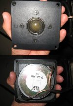
See attached image, I borrowed the picture from the German forum I linked to in post #32. The dome seems to be some kind of impregnated fabric.
I can't find any info on the tweeters or the frequency range they have to reproduce in the ATL speakers.
BTW, that foam damping is near the driver and it's on a wall surface (which is worse). That portion of the cabinet also looks "cramped" for space (..even if it does expand into the lower portion of the cabinet).
Compared to the minimonitors, space is actually abundant in the ATL speakers. The Minimonitors use much bigger filter components and the sections for bass/mid and treble needed to be built separately and placed in different locations in the cabinet. I ended up putting the bass/mid part of the filter on the rear panel between reflex port and terminals and the treble section on a side panel close to the tweeter.
Attachments
A flimsy box will make a proper design harder. Especially in a 2-way floorstander with large woofer, we have too many issues to solve (and often we have to sacrifice something). It will be easier for example if the tweeter is close to one side than in the center of the panel.
I have mentioned 2 factors affecting good image:
1) There should be no non-signal sound coming from speaker (cone, mechanic, enclosure, port, etc)
2) The intended sound must come to ears completely and timely. This is why positioning etc affect "stereo" imaging.
Point #2 can be worked around, but point #1 is NOT.
Well, a two way floor stander with a large woofer is a problem to start with as I know of no drivers save pro PA components that are suitable for this. You mention obvious empiricals. I am talking practicals. Fix the first 90%, then worry about the rest. I don't care if the box is cardboard, the crossover is 90% of the result. But then again, I have only been building speakers for 40 years. I could build them for another 40 years and not know half of what is important. The are easy to do fair, really complicated to do well.
Simon, last statement, how true. I have just about given up on the Seas 27TBFC/G as I can't seem to tame it breakup range ( 26.5K). Shame, as it is otherwise very low distortion and provided detail that is quite natural. Actually, I am giving up on metal drivers all together. Zaph, Dayton, Seas. It is a matter of trade offs.
So, you are suggesting the B&W kevlar cones have a much lower Q in their breakup region? Is this easier to either tame or ignore? Would that suggest a carbon weave in a otherwise very low modulus matrix be well behaved?
So, you are suggesting the B&W kevlar cones have a much lower Q in their breakup region? Is this easier to either tame or ignore? Would that suggest a carbon weave in a otherwise very low modulus matrix be well behaved?
Personally I'm not a big fan of kevlar or its breakup characteristic.So, you are suggesting the B&W kevlar cones have a much lower Q in their breakup region? Is this easier to either tame or ignore? Would that suggest a carbon weave in a otherwise very low modulus matrix be well behaved?
The main advantage it has in that application is the fact that its not a homogenous material like paper, its a weave, and B&W exploit the fact that the bending waves propagate at different speeds in different directions along the weave, as described. (There's a whole section in the white paper about the Nautilus 801 design that goes into the theory behind this which is interesting reading)
I prefer the breakup characteristics of paper over kevlar, but of course paper is homogenous so is radially symmetric, which is bad as far as standing waves go. That's why I'm quite pleased with some of the results I've had with asymmetric damping patterns on paper cones - the "character" of the breakup is still that of paper, but with a large reduction in breakup resonances as measured from a distance. The right pattern of damping also seems to help stabilise and control bell modes as well as the radial bending modes.
Not wanting to operate a speaker in cone break-up is somewhat at odds with your choice of Avatar image 😉
Agreed.
My problem with operating drivers in the cone break-up range is that the break-up seems to become very prominent past a certain point in SPL output.
I tried playing a rap track (loud) through my new speakers. Set off well, the bass driver was moving maybe 10mm p/p (so plenty of low end), but then some treble came along and made the sound so bright I had to switch it off. It was the sort of sound that'd make you wince.
Turn it down to slightly more reasonable levels, and it sounded fine again.
The only way around this, so far as I can tell, is to let something else take the top end.
I suppose this is coming down to the subjective nature of "performance".
Chris
need not be cone breakup at all
sounds more like xo issue
some speaker could very well have xo slopes etc working ok
and then have just the SPL/attenuation matching all wrong
beats me why, but it does happen more often than you expect
if so, it could be a relatively simple matter
might not get perfect, but could still help a lot on what you describe
I gotta enjoy people saying they hate metal cones. Flipping awful things. Supersonics to make your ears bleed! 😀
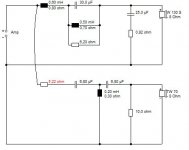
Here's the classic BBC crossover to give Jitter some ideas, really the state of the art still! You can sometimes get away with second order on the tweeter if the driver is well behaved and a RC tank across the bafflestep coil does nice things to phase while killing some breakup beyond crossover, but second order bass is essential to tame breakup modes. Notice the RCL trap to tame the bass midrange peak on small 5" drivers. It works particularly well with low inductance drivers, because the bafflestep coil is exactly the voice coil inductance for bookshelf use. And with further elegance, the bass capacitor is twice the bass Zobel value for reasons you may understand if you pay attention to third order butterworth type filters.
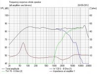
I include the AWFUL response without the trap, just for giggles. This is why people don't much use second order on bass commercially. The trap is VERY expensive. FWIW, the little resistor on the bass capacitor is essential to good phase. 😀
Here's the classic BBC crossover to give Jitter some ideas, really the state of the art still! You can sometimes get away with second order on the tweeter if the driver is well behaved and a RC tank across the bafflestep coil does nice things to phase while killing some breakup beyond crossover, but second order bass is essential to tame breakup modes. Notice the RCL trap to tame the bass midrange peak on small 5" drivers. It works particularly well with low inductance drivers, because the bafflestep coil is exactly the voice coil inductance for bookshelf use. And with further elegance, the bass capacitor is twice the bass Zobel value for reasons you may understand if you pay attention to third order butterworth type filters.
I include the AWFUL response without the trap, just for giggles. This is why people don't much use second order on bass commercially. The trap is VERY expensive. FWIW, the little resistor on the bass capacitor is essential to good phase. 😀
Attachments
Last edited:
See attached image, I borrowed the picture from the German forum I linked to in post #32. The dome seems to be some kind of impregnated fabric.
I can't find any info on the tweeters or the frequency range they have to reproduce in the ATL speakers.
Compared to the minimonitors, space is actually abundant in the ATL speakers. The Minimonitors use much bigger filter components and the sections for bass/mid and treble needed to be built separately and placed in different locations in the cabinet. I ended up putting the bass/mid part of the filter on the rear panel between reflex port and terminals and the treble section on a side panel close to the tweeter.
No, I meant inside the back-plate of the tweeter. 😉 (..there is a reason you pay more for those Scan-Speaks..)
A fairly simple test is disconnecting the ATL's mid-bass drivers and mounting them in card board box's of similar size/shape (to the ATL's). (..use tape to "seal" the edges of the box.) Play them as "full-range" drivers and see if you start getting depth.
@ chris, I'm also inclined to think diffraction contributes. It has two signatures that don't relate to the signal: it's fixed delay (with some frequency dependence) and its level dependence.
On the other hand, I'm of the mind that the greater the delay of the second source the better, and will involves less of the midband frequencies, and will be slightly lower in level.
Jay, if I understand what you are suggesting, front panel reflection keeps the sound in half space for a time where diffraction and the potential for room reflections are less.
A rule of thumb maybe, but not necessarily true.It is common rule of thumb: smaller speaker images better, bigger speaker produces lower frequencies (We are talking about the same driver here).
A speaker that images well presents a soundstage that has depth and width, and generally the source of sound appears to be behind the speakers themselves by some distance, while a speaker that images poorly often localizes to its actual physical location, as noted by the original poster.
Why ? There was a lot of discussion about this in a couple of other threads not long ago and it was suggested by several that having a speaker acting as a point source (particularly at high frequencies) with low diffraction is a key part of maintaining the illusion that the speaker is not the source of the sound you hear, and making the speaker itself "disappear".
This means that for example in the range of the tweeter you want to be hearing sound only from the exact location of the tweeter, with no baffle diffraction contribution from the edges of the baffle. The source of the sound should be physically small and narrow.
If you have a large baffle with a large amount of high frequency diffraction from the edges you don't have a point source any longer, you have a first arrival from the tweeter in the middle, a second arrival from the edge that is angled closest to you (depending on speaker toe in) then shortly after that a third arrival.
If the speaker is large each one of those comes from a different horizontal azimuth location, and the human hearing system is VERY sensitive to horizontal azimuth in the front hemisphere, its been found that we can detect location differences as small as 1 or 2 degrees in horizontal azimuth - more than enough to detect a difference between the angle to the left edge and right edge of a large speaker cabinet at a normal listening difference.
Pure speculation on my part here, but I wonder if the brain is somehow able to asess the size of the sound source by noting the angular range over which the three correlated sounds arrive and infer the size and location of the sound source from that.
On the other hand a true point source which is exceptionally narrow in the horizontal plane containing no correlated diffraction/reflection can only mean a sound source distance of "infinity" to any such estimation method that the brain might use. In nature only a sound source very far away would be this "narrow" in azimuth.
Whether that's the mechanism behind how we perceive it or not, it does seem that minimising diffraction at high frequencies so that a speaker approaches a point source as closely as possible is necessary for the speaker to disappear and allow an image to project from behind the speaker.
A small speaker with diffraction probably does this better than a large speaker with diffraction because both the time delay and azimuth offset of the diffracted signals is reduced, however a speaker (narrow or wide) which doesn't diffract works better than either of the other two cases.
It's been my experience that a large speaker with vertically aligned drivers can image just as well if not better than a small speaker provided that high frequency baffle diffraction is thoroughly taken care of - and it usually isn't in most designs. (If there is no diffraction > ~2Khz it doesn't matter if the baffle is wide or narrow IMHO)
This can mean using a wave guide for the tweeter, extensive curving of the cabinet, (more than the typical 3/4" round-over on a flat baffle edge) foam/felt absorption, or a combination of the above.
To do a really thorough yet DIY practical job of diffraction elimination at high frequencies though, I think it really does take a waveguide - rounding of edges or foam on its own really isn't enough.
A lot of other things are needed to get really good imaging, including a very flat high frequency response, but its probably diffraction that is most overlooked. A lot of people's ideas of dealing with diffraction are to simply horizontally offset the tweeter on the baffle and adjust the EQ of the network to compensate the on axis response to be as flat as possible.
That might make the on axis response measure flatter but it hasn't in any way reduced the amplitude of the diffraction, nor does it make the speaker become a point source approximation. Round-overs on the edge of flat baffles are also rarely large enough in radius to do any good to a low enough frequency and are therefore typically only cosmetic.
Use vertically aligned drivers, eliminate diffraction at high frequencies, get the crossover design right, (especially inter-driver phase tracking and overall amplitude response flatness) and I think you're 2/3rd of the way towards getting good imaging...
Last edited:
Very interesting, DBMandrake. I do suspect our brains/ears are VERY sensitive to timing of signal arrival as you say. We can locate a twig snapping VERY accurately. I was impressed and gobsmacked when Michelino rebuilt his cabinets and crossover to use an old classic plastic KEF B200 with a modern Vifa XT19 waveguide tweeter:
Just dig that time alignment. Shame about the woolly reflex, because closed box is what gets your feet tapping to the rythym IMO. But very nice!
An externally hosted image should be here but it was not working when we last tested it.
Just dig that time alignment. Shame about the woolly reflex, because closed box is what gets your feet tapping to the rythym IMO. But very nice!
Well, a two way floor stander with a large woofer is a problem to start with as I know of no drivers save pro PA components that are suitable for this. You mention obvious empiricals. I am talking practicals.
No, I was not talking empirical(?), and I will not as I have no interest in discussing textbook theory. I prefer to be down to earth (see last paragraph).
Fix the first 90%, then worry about the rest. I don't care if the box is cardboard, the crossover is 90% of the result. But then again, I have only been building speakers for 40 years. I could build them for another 40 years and not know half of what is important. The are easy to do fair, really complicated to do well.
To do it fair, just stick with the 90%. To do anything well, we need motivation. But being perfectionist is actually much easier than being effective, because there is "cost-no-objection" with being perfectionist. Being effective is harder because we need to know the level of impact of everything we do, not only to us but to others who expect something from our work.
My previous suggestion to the flimsy speaker was simple, just put the tweeter closer to one side. But DBMandrake suggested to put it vertically aligned? That's something new to me.
A lot of people's ideas of dealing with diffraction are to simply horizontally offset the tweeter on the baffle and adjust the EQ of the network to compensate the on axis response to be as flat as possible.
If your requirement is for the speaker to image well from any location, "slanting" baffle approach is like a big joke. Bigger joke is to listen to music from a sofa in certain location between left and right speaker

Use vertically aligned drivers.
Do you mean vertically as not slanted or without horizontally offset, or in vertical line without tweeter offset to one side of the enclosure? I believe the former. Slanting alignment is ime more relevant with the effort to position the woofer relative against the room/floor and enclosure base (than to timeline diffraction).
Last edited:
Not sure if I follow what you're saying, I was referring to the practice of horizontally offsetting a tweeter to one side, not sloping the baffle backwards for time alignment.If your requirement is for the speaker to image well from any location, "slanting" baffle approach is like a big joke. Bigger joke is to listen to music from a sofa in certain location between left and right speaker
I mean that looking from the front there should be a vertical line through the centre of all the drivers. In other words no funny configurations such as side by side or diagonal driver placement, and no offsetting just a tweeter to one side but not the woofer/mid.Do you mean vertically as not slanted or without horizontally offset, or in vertical line without tweeter offset to one side of the enclosure? I believe the former. Slanting alignment is ime more relevant with the effort to position the woofer relative against the room/floor and enclosure base (than to timeline diffraction).
Offsetting just one driver to the side disturbs the horizontal polar response of the speaker and is not conducive to good imaging. If you feel you must offset the tweeter then the woofer/mid should be offset by the same amount to maintain a vertical line, although I'm not in favour of such asymmetric layouts in general as they are usually done to try to combat the effects of diffraction but IMHO are the wrong approach and only improve the on axis frequency response without reducing actual diffraction in any way.
You now also have the added complexity of having to have a mirror image design for left and right speakers (and the possibility of the listener having them the "wrong" way around) instead of both speakers being identical and interchangeable.
Last edited:
What you're probably noticing is simply the non flatness of frequency response - resonances in the treble become more and more noticeable and obnoxious as SPL increases even if the resonances themselves don't get any worse. EG, a lumpy frequency response that sounds ok at a low SPL may not sound ok at a higher SPL even if the measured frequency response curve was identical but just louder. This is a perceptual thing.Agreed.
My problem with operating drivers in the cone break-up range is that the break-up seems to become very prominent past a certain point in SPL output.
I tried playing a rap track (loud) through my new speakers. Set off well, the bass driver was moving maybe 10mm p/p (so plenty of low end), but then some treble came along and made the sound so bright I had to switch it off. It was the sort of sound that'd make you wince.
Turn it down to slightly more reasonable levels, and it sounded fine again.
So yes, there are probably significant resonances in the driver(s) you're listening to in the treble, which are probably caused by cone breakup, but as I said before cone breakup doesn't inevitably lead to resonances, only if symmetrical standing wave patterns are allowed to form.
- Status
- Not open for further replies.
- Home
- Loudspeakers
- Multi-Way
- what makes sound "stick" to speakers?