welcome to the club scouliki. thats what i been raving about c5. for me the winner was mundorf .1 but im also tempted to try something higher valued as i have a pair of jantzen .33 laying about. those would be as big as the c9 cap!
Hi presapian, which Mundorf is that?
After a LM3875 dissapointed me because of my 4 ohms speakers i've discovered this huge and popular thread.
I would be verry hapy to give it a try as i understand LM3886 is more capable to drive 4 ohms speakers.
Can anyone guide me where to find a pcb layout (eagle, pdf) to etch my own boards ?
I have high hopes and expectations from this design.
Thanks !
I would be verry hapy to give it a try as i understand LM3886 is more capable to drive 4 ohms speakers.
Can anyone guide me where to find a pcb layout (eagle, pdf) to etch my own boards ?
I have high hopes and expectations from this design.
Thanks !
Can anyone guide me where to find a pcb layout (eagle, pdf) to etch my own boards ?
I have high hopes and expectations from this design.
Look at the start of the thread, Penasa posted the PCB layout (single side), otherwise, also in this thread Russ White posted his double side monoblock design.
Or if you want to wait one month or two I'll start a GB for PCBs of my variation.
Hi presapian, which Mundorf is that?
sorry for the late reply. it's supreme. 🙂
How this amplifier is driving some 4ohm speakers ? As far as i was reading the thread everybody is referring to 8ohm speakers.
It will do a fine job. You have to change the voltages of the PSU to power different speakers best.
Uriah
Uriah
I have put that exploration for last, but I do think it is also desirable to increase the current gain of the Holland current pump. Just today, I think I have been hitting the voltage limit of the LM318 output, the amp tends to click out and kick back in at the limits. Has anyone experienced this?
... the amp tends to click out and kick back in at the limits. Has anyone experienced this?
That's probably the SPiKe protection of the LM3886 kicking in. It typically happens at high rails (greater than +/- 32 V DC), low load impedances (less than 8 ohms), high amplitudes, and unstable compensation (i.e. C34 too low, C10 too high, etc.).
It only happens with a certain power supply configuration, so I guess something is going on at the rails since I have turned the volume up much higher before.
Does anybody knows it exists an F version of MyRef ampli? As i was reading here latest is C version and the FE variation.
Does anybody knows it exists an F version of MyRef ampli? As i was reading here latest is C version and the FE variation.
The only official versions by Mauro Penasa are Rev A, Rev B and Rev C.
Also official but not public are the My_Evo and My_Evo Rev A.
All other versions like the X-Calibre, Rev D and my My_Ref Fremen Edition (FE) are unofficial variations by other people.
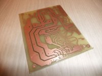
I've received my pcb's based on Rudi's design. Hopefully Mouser will send me the componentes fast.
Also received two monster toroids 2x26V 200VA (secondary 1,5mm diameter).
I'm not decided whether to use one toroid for every channed or use only one toroid for both channels. They are huge... 🙂 2,2kg/trafo
Also received two monster toroids 2x26V 200VA (secondary 1,5mm diameter).
I'm not decided whether to use one toroid for every channed or use only one toroid for both channels. They are huge... 🙂 2,2kg/trafo
Attachments
Last edited:
Hiss problem
Hi everybody.
My amp developed a problem. After i switch it on, i get hiss on both channels. Actually in one channel the hiss is barely noticable, in the other its stronger. I can hear the hiss at a distance of about 40cm from the speaker. I can also barely hear a phasing tone through the hiss. The weird part is that when i first noticed this problem (about 2 weeks ago), the hiss and tone dissapeared after some minutes of operation. When i switched off the amp and then switch it on again, before it cooled off there was no problem. If i let it cool and then switch on again the problem reappeared. Now the hiss is constant no matter if the amp was warm or cold- only the phasing tone dissapears. Any ideas are welcome
LM318 Regulation
Hallo skouliki,
If it was an older amplifier, I would check and change the electrolytic caps. I´m not sure if this is applicable to your (probably not so old) amplifier.
I have a question myself, regarding regulation of the LM318. I use teddyregs on other equipment a lot, and read here, that they have been used for LM318-regulation in the myref-amp with success.
For teddyregs see: Teddyreg Ultra Low Noise Regulator
I would like to try this myself and wonder how to best insert the teddyreg into the power feed. The obvious choice would be to omit R1 and R4 and use the pinholes for input/output of the reg and feed maybe 14 Volts into ZD1/2 and C11 and C6.
So here are my questions: Would it be beneficial to leave the Zener Diodes and C11/6 in place to get the desired 12V, or isn´t it better to omit ZDs as well and set the teddyreg output straight to 12 V. ZD1/2 and C6/11 could then be used for the teddyreg output decoupling (film cap) and/or load resistor.
I etch the regs myself, so I could make the PCBs a little bit smaller and the empty part-slots wouldn´t be unused.
Is it "that easy", or do the ZDs maybe provide additional filtering or stability, even on the teddyregs?
Can I just leave them out?
That´s all for today, Thank you.
Florian
Skouliki:The warm-up duration suggests a dry or fractured joint, or even a flaky resistor end-cap. Check the fast-ons for tight seating. Also check the input connector block for a tight joint. Try reflowing all joints on the board after that. If the hiss persists, further debugging is required.
Kumori: There are upgrades to the shunt regulator that can be retrofitted to the Rev C/E. In particular, Dario's zener/resistor/transistor mod should be a big audible improvement, provided the other components in the signal chain are good enough.
Kumori: There are upgrades to the shunt regulator that can be retrofitted to the Rev C/E. In particular, Dario's zener/resistor/transistor mod should be a big audible improvement, provided the other components in the signal chain are good enough.
With retrofitting, do you mean off- or on-board.
Since the parts count is a little bit higher, I would make a small PCB and insert this in place of R1/R4.
1) One option is to go the whole hog, make two separate perfboards/PCBs and replace R1, R4, ZD1, ZD2 - connect wires from the boards suitably.
2) A simpler option is to retain R1, R4 (omit the LM317/337 current sources). Just replace ZD1 by D9, R3, Q1 and ZD2 by D10, R4, Q2. This can be done without a perfboard/PCB, but may be neater with separate small boards.
In both cases, try to keep the leads to the main board short to avoid pickup/hum etc.
- Home
- Amplifiers
- Chip Amps
- My "audiophile" LM3886 approach